Review
. 2013 Jun 21;5(12):5225-40.
doi: 10.1039/c3nr00037k.

Actuators based on liquid crystalline elastomer materials

Affiliations
Review

Actuators based on liquid crystalline elastomer materials

Hongrui Jiang et al. Nanoscale. .

Abstract

Liquid crystalline elastomers (LCEs) exhibit a number of remarkable physical effects, including the unique, high-stroke reversible mechanical actuation when triggered by external stimuli. This article reviews some recent exciting developments in the field of LCE materials with an emphasis on their utilization in actuator applications. Such applications include artificial muscles, industrial manufacturing, health and microelectromechanical systems (MEMS). With suitable synthetic and preparation pathways and well-controlled actuation stimuli, such as heat, light, electric and magnetic fields, excellent physical properties of LCE materials can be realized. By comparing the actuating properties of different systems, general relationships between the structure and the properties of LCEs are discussed. How these materials can be turned into usable devices using interdisciplinary techniques is also described.


Figures

Figure 1
Figure 1
An LCE actuator and its components: a) silicon carrier during batch manufacturing, b) elastomer mounted onto the finished gripper mechanism (elastomer dimensions: 16×4×0.030 mm3; arm length: 20 mm; frame dimensions: 22×25 mm2). c) Open (left) and closed (right) liquid-crystalline elastomeric microgripper on applying an electrical power, where the nematic-toisotropic transformation induces changes of the liquid-crystalline elastomer film length that causes the strain. d) Thermal contraction–expansion (λ) as a function of the heating–cooling time (left) and as a function of the variation of voltage (right) for the microgripper. Reprinted with permission from ref. [66]. Copyright 2009, Wiley-VCH.
Figure 2
Figure 2
a) Solid model of a half of an LCE microvalve. b) Top view of the microchip before assembly. c) Snapshot pictures during the actuation of the LCE microvalve. The actuator pushes itself at the end of the extension into the microchannel opening: moving of the microvalve-structure before the assembly of the microchip (top), and moving of the ready LCE-silicon structure through an artificial hole in one side of the chip (bottom). Reprinted with permission from ref. [67]. Copyright 2011, Wiley-VCH.
Figure 3
Figure 3
Micrometer-sized nematic LCE actuators consisting of a pillar array. a) Experimental setup used to prepare the responsive pillars. b) Top view (under an optical microscope) of the pillar pattern obtained by the imprint in the nematic liquid crystal elastomer. (Inset) Zoom on the structure (pillar diameter = 20 µm). Reprinted with permission from ref. [59]. Copyright 2006, American Chemical Society.
Figure 4
Figure 4
a) The nematic thiolene monomer and tetrafunctional nematic crosslinker used to prepare main-chain LCEs. b) SEM image of a surface covered with cylindrical pillars. Reprinted with permission from ref. [68]. Copyright 2009, American Chemical Society
Figure 5
Figure 5
a) Schematic of the setup for demonstrating the deflection of a laser beam due to the photoinduced bending of an azo-CLCP cantilever. b) Deflection angle of the probe He-Ne laser beam as a function of the power density of a pump Ar+ laser beam. The insert shows the azo-CLCP film and its surface with silver film. c) The position of the probe laser beam reflected from the azo-CLCP surface with silver film at different time moments upon (top) unblocking and (bottom) blocking the laser beam, upper numbers correspond to time in seconds. Reprinted with permission from ref. [76]. Copyright 2009, Optical Society of America.
Figure 6
Figure 6
a) Cilia are made with two separate parts of CLCPs by separately polymerizing the two parts. b) Schematic representation of light-driven cilia producing an asymmetric motion controlled by the spectral composition of the light. c) Frontal view of actuation of multicolour cilia in water addressed with visible (4 mW cm−2) and ultraviolet (9 mW cm−2) light. All scale bars indicate 0.5 mm. Reprinted with permission from ref. [32]. Copyright 2009, Macmillan Publishers Ltd.
Figure 7
Figure 7
a) A schematic representing the assembled prototype of a micropump. b) Photo of the experimental prototype (1. inlet, 2. press plate, 3. photodeformable material, 4. outlet, 5. pump membrane, 6. pump chamber). c) Exert the photodeformable film on pump membrane (1. press plate, 2. photodeformable film, 3. pump membrane, 4. pump chamber). Reprinted with permission from ref. [77]. Copyright 2010, Springer-Verlag.
Figure 8
Figure 8
A tunable lens actuated by photo-polymer: (a) Top glass slab; (b) bottom glass slab; side views of the lens cell in (c) non-focusing and (d) focusing states; (e) liquid lens at the non-focusing state; (f) liquid lens at a focusing state; and (g) measured focal length of the lens at different power densities of stimulating light. Reprinted with permission from ref. [78]. Copyright 2009, OSA.
Figure 9
Figure 9
A light-driven plastic motor with an LCE laminated film. a) Schematic illustration of a light-driven plastic motor system, showing the relationship between light irradiation positions and a rotation direction. b) Series of photographs showing time profiles of the rotation of the light-driven plastic motor with the LCE laminated film induced by simultaneous irradiation with UV (366 nm, 240 mW cm−2) and visible light (>500 nm, 120 mW cm−2) at room temperature. Reprinted with permission from ref. [79]. Copyright 2008, Wiley-VCH.
Figure 10
Figure 10
An LCE film that can swim on a water surface. a) A single video frame showing the shape deformation of an LCE sample immediately following illumination. b) Illustration of how the sample shape changes and hence interacts with the fluid below it. The left figure shows the initial deformation of the sample on illumination. c) A series of video frames as the LCE sample moves away from the area of sustained illumination. d) Irregular rectangular LCE sample floating on ethylene glycol first folds then swims away when illuminated. Reprinted with permission from ref. [80]. Copyright 2004, Macmillan Publishers Ltd.
Figure 11
Figure 11
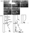
A unidirectional motion of a CLCP sample, mimicking an inchworm walk. a) Series of photographs showing time profiles of the photoinduced inchworm walk of the CLCP-laminated film by alternate irradiation with UV (366 nm, 240 mW cm−2) and visible light (>540 nm, 120 mW cm−2) at room temperature. b) Schematic illustrations showing a plausible mechanism of the photoinduced inchworm walk of the CLCP laminated film. Upon exposure to UV light, the film extends forward because the sharp edge acts as a stationary point (the second frame), and the film retracts from the rear side by irradiation with visible light because the flat edge acts as a stationary point (the third frame). Reprinted with permission from ref. [81]. Copyright 2009, The Royal Society of Chemistry.
Figure 12
Figure 12
Series of photographs showing time profiles of the motion of a flexible robotic arm of a CLCP laminated film induced by irradiation with UV (366 nm, 240 mW cm−2) and visible light (>540 nm, 120 mW cm−2) at room temperature. Arrows indicate the direction of light irradiation. Reprinted with permission from ref. [81]. Copyright 2009, The Royal Society of Chemistry.
Figure 13
Figure 13
A CLCP-based microrobot. a) Photographs showing the microrobot picking, lifting, moving, and placing an object to a nearby container by turning on and off the light (470 nm, 30 mW cm−2). Length of the match in the pictures: 30 mm. Object weight: 10 mg. b) Schematic illustrations of the states of the microrobot during the process of manipulating the object. The insert coordinate indicates the moving distance of the object in vertical and horizontal directions. White and black arrows denote the parts irradiated with visible light. Reprinted with permission from ref. [82]. Copyright 2010, The Royal Society of Chemistry.
Figure 14
Figure 14. A photo-driven oscillator
a) A CLCP film is mounted vertically (starting position shown with dashed lines) and oscillates around the horizontal plane of incidence of the laser beam with full oscillation angle. b) Snapshots of the oscillating azo-CLCP at different power levels: (1) 76 mW, (2) 85 mW, (3) 90 mW, (4) 100 mW, (5) 107 mW, (6) 121 mW, (7) 143 mW. Reprinted with permission from ref. [83]. Copyright 2010, The Royal Society of Chemistry
Figure 15
Figure 15. Actuation based on an LCE-CNT composite
(a–c) Localised structuring process and actuation scheme of the LCE-CNT composite. a) Structuring and stretching sequence: i. Mould alignment and gearing and LCE-CNT stretching; ii. Punch releasing and LCE mesogen alignment (mesogens are drawn as lines to illustrate). b) Ambient state, light source is OFF. c) Actuated state: feature contracts when the light is ON. d) Optical stereoscopic picture of a strip of the stretched LCE-CNT composite, where the stamping process pushes the composite out of the die mould to form the “bubbled” pattern. Inset: 3D topographic change of the “bubble” under photo actuation. Reprinted with permission from ref. [95]. Copyright 2011, Wiley-VCH.
Figure 16
Figure 16
Concept of artificial heliotropism. a) 3D schematic of the system. b, c) 3D schematic of the heliotropic behavior. The actuator(s) facing the sun contracts, tilting the solar cell towards the sunlight. Reprinted with permission from ref. [96]. Copyright 2012, Wiley-VCH.
Figure 17
Figure 17
Optical images of photo actuation of a blank LCE and an SWCNT–LCE nanocomposite films. The films have a dimension of 4 cm × 0.5 cm × 0.7 mm. The irradiation intensity of the white light is 230 mW cm−2. a) The initial state of the blank LCE and SWCNT–LCE nanocomposite films. b) Comparison of the two films under irradiation. The blank LCE does not deform after being illuminated for several minutes. In contrast, SWCNT–LCE nanocomposite film starts conspicuous contraction after about 5 seconds, and reaches the stable length, which is about 2/3 of the initial length, after about 10 seconds. (c) The SWCNT–LCE nanocomposite film recovers to its initial length about 9 seconds after the light source is switched off. Reprinted with permission from ref. [92]. Copyright 2011, The Royal Society of Chemistry.
Figure 18
Figure 18
Heliotropic behavior of a 2-actuator-unit device in an in-field test (a, b) and resultant photocurrent increase (c). Initially the device was blocked from the sunlight. a) The actuator was just exposed to the sunlight and began to contract. b) After 110 s, the actuator reached full contraction and the solar cell was tilted by 16.3°. c) Photocurrent increase owing to artificial heliotropism with a single actuator unit. The incident light was kept at 100 mW cm− 2 but was from different directions. d) The altitude-azimuth coordinate system used. The origin was the center of the actuator facing the light. The normal incidence direction was 0° altitude, 180° azimuth. Reprinted with permission from ref. [96]. Copyright 2012, Wiley-VCH.
Figure 19
Figure 19
Photocurrent increase owing to artificial heliotropism by a prototype device with 3-actuator units (a) and its heliotropic behavior in laboratory (b, c) tests. An altitude-azimuth coordinate system similar to Figure 18 (d) was used for data acquisition for (a). The origin was the center of the actuator in the middle. Irradiation was from a white light source (intensity: 100 mW cm −2; partially collimated; spot diameter: 101.6 mm; 0° altitude; 180° azimuth) for (b, c). b) Before irradiation. c) 30 s after irradiation. Reprinted with permission from ref. [96]. Copyright 2012, Wiley-VCH

Similar articles

Cited by

References

    1. Ionov L. J. Mater. Chem. 2010;20:3382.
    1. Lendlein A. J. Mater. Chem. 2010;20:3332.
    1. Yu Y, Ikeda T. Angew. Chem.-Int. Edit. 2006;45:5416. - PubMed
    1. Cheng F, Zhang Y, Yin R, Yu Y. J. Mater. Chem. 2010;20:4888.
    1. Warner M, Terentjev EM. Liquid Crystal Elastomers. Oxford: Oxford University Press; 2003. - PubMed

Publication types