. 2013:4:1808.
doi: 10.1038/ncomms2839.

Free-electron gas at charged domain walls in insulating BaTiO₃

Affiliations
Free PMC article

Free-electron gas at charged domain walls in insulating BaTiO₃

Tomas Sluka et al. Nat Commun. 2013.
Free PMC article

Abstract

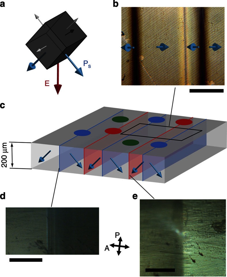
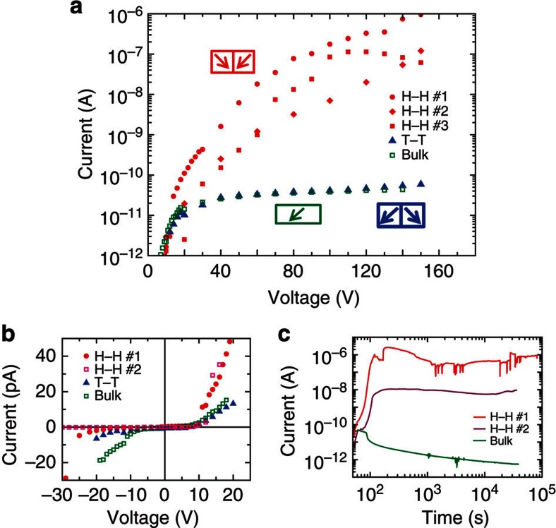
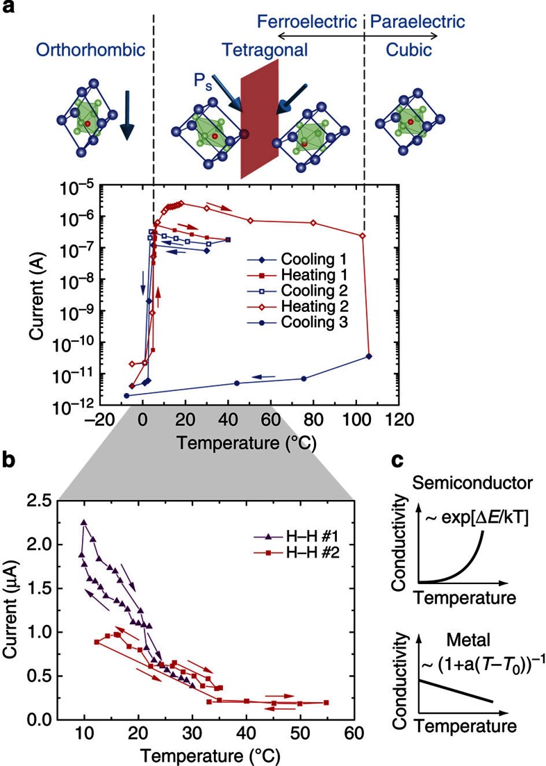
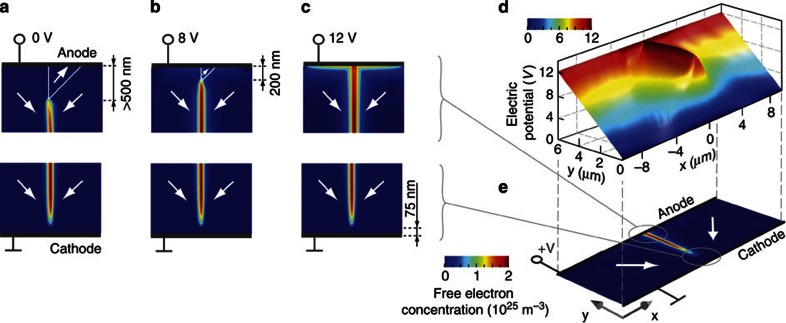
Hetero interfaces between metal-oxides display pronounced phenomena such as semiconductor-metal transitions, magnetoresistance, the quantum hall effect and superconductivity. Similar effects at compositionally homogeneous interfaces including ferroic domain walls are expected. Unlike hetero interfaces, domain walls can be created, displaced, annihilated and recreated inside a functioning device. Theory predicts the existence of 'strongly' charged domain walls that break polarization continuity, but are stable and conduct steadily through a quasi-two-dimensional electron gas. Here we show this phenomenon experimentally in charged domain walls of the prototypical ferroelectric BaTiO₃. Their steady metallic-type conductivity, 10(9) times that of the parent matrix, evidence the presence of stable degenerate electron gas, thus adding mobility to functional interfaces.


Figures

Figure 1
Figure 1. Charged domain walls in tetragonal BaTiO3.
(a) Poling of the crystal in a [110]c-like direction (red arrow) allows two equally preferred ferroelectric domain states (blue arrows) out of the six permitted (blue and grey arrows). When the frustrated poling is applied during a slow paraelectric-ferroelectric PT, tail-to-tail (bd) and head-to-head (b,c,e) domain walls are formed. (b) Top view micrograph with light transmitted through the sample in the [110]c direction. Scale bar, 200 μm. (c) Out-of-scale cartoon illustrates a 200 μm thick (110)c sample with 5 × 5 mm2 top surface covered with 200 μm diameter and 400 μm period electrodes. The domain walls are irregularly distributed with period from 100 to 300 μm. (d,e) Side view micrographs with light transmitted in the [001]c direction show the tail-to-tail domain walls (scale bar, 100 μm) and head-to-head domain wall (scale bar, 25 μm), respectively. P denotes polarization of incident light and A polarization filter on transmitted light.
Figure 2
Figure 2. Conduction through charged domain walls in BaTiO3.
(a) Semilogarithmic-scale room-temperature IV characteristics showing up to 105 times higher conduction through electrodes touching head-to-head (H–H) charged domain walls compared with the bulk and tail-to-tail (T–T) domain walls. (b) Linear-scale IV curve showing ~8 V conduction threshold indicating barriers between electrodes and ferroelectric. Each datapoint in (a,b) is acquired 1 min after step change of applied voltage, hence, the values include transient currents. The difference between H–H current and bulk is, therefore, underestimated here. The steady current through the bulk (at V=100 V after>660 min) is 6 × 10⁻¹³ A, while H–H wall reaches steady 10−6 A, shown in c. The current increase during first 200 s in c corresponds to slowly applied voltage. Attributing the current difference between H–H domain wall and the bulk to domain wall itself, its intrinsic conductivity is 108−1010 times that of the bulk.
Figure 3
Figure 3. Switching metallic-type properties of charged domain walls.
(a) Current–temperature dependence shows switching of the metallic-type conductivity when a 90° head-to-head (H–H) charged domain wall is created and annihilated at PTs. The domain walls formed in tetragonal BaTiO3 cannot exist in the orthorhombic and paraelectric phases as illustrated in the cartoon. The charged domain wall is annihilated at both transitions from the tetragonal phase. The annihilation at the transition to the paraelectric phase is permanent in this case. The conductivity characteristic shows change from metallic-type temperature dependence and magnitude to thermally activated conduction typical for wide-bandgap semiconductor bulk BaTiO3. (b) Linear-scale current–temperature dependence showing pronounced positive temperature coefficient indicating thermally non-activated (that is, metallic-type) conduction at domain walls as illustrated in c.
Figure 4
Figure 4. Connecting a charged domain wall and electrodes by an applied voltage.
(ac) Colour-scale map of the phase field calculated free-electron concentration at a head-to-head domain wall when an electric potential is being applied. The wedge-like domain disconnects the free-electron gas from the anode when the potential difference is below 8 V. The free-electron gas is permanently disconnected from the cathode. (d) Colour-scaled landscape of electric potential in the vicinity of the domain wall when 12 V is applied. The charged domain wall is at equipotential with the anode. (e) Illustration of the polarization (arrows) and free-charge (color-scale) distribution under the applied 12 V.
Figure 5
Figure 5. Schematic of the band structure at head-to-head domain wall.
Conduction band, EC, drops below the Fermi level, EF, at head-to-head strongly charged domain walls (sCDW). At 0 V, (a), sCDW is separated from both electrodes by dielectric regions, which are exposed to high electric fields (given by the potential slope). The electric field at the anode has a depolarizing direction and nucleates an anti-polar domain as seen in Fig 4a. At the cathode, the field has a poling direction. (b) Under an applied potential difference, the barrier at the anode is annihilated and the electron gas at sCDW connects the electrode. The dielectric barrier at the cathode is exposed to the applied potential difference. Theory allows high Fowler–Nordheim tunnelling current through the barrier with realistic parameters. Additional mechanisms, especially those related to oxygen vacancy accumulation, may contribute.

References

    1. Mathur N. D. et al.. Large low-field magnetoresistance in La0.7Ca0.3MnO3 induced by artificial grain boundaries. Nature 387, 266–268 (1997).
    1. Ohtomo A. & Hwang H. Y. A high-mobility electron gas at the LaAlO3/SrTiO3 heterointerface. Nature 427, 378–380 (2004). - PubMed
    1. Thiel S., Hammerl G., Schmehl A., Schneider C. W. & Mannhart J. Tunable quasi-two-dimensional electron gases in oxide heterostructures. Science 313, 1942–1945 (2006). - PubMed
    1. Chakhalian J. et al.. Magnetism at the interface between ferromagnetic and superconducting oxides. Nat. Phys. 2, 244–248 (2006).
    1. Tsukazaki A. et al.. Quantum hall effect in polar oxide heterostructures. Science 315, 1388–1391 (2007). - PubMed

Publication types

LinkOut - more resources