. 2013 May 8:7:53.
doi: 10.3389/fncom.2013.00053. eCollection 2013.

Detecting global form: separate processes required for Glass and radial frequency patterns

Affiliations

Detecting global form: separate processes required for Glass and radial frequency patterns

David R Badcock et al. Front Comput Neurosci. .

Abstract

Global processing of form information has been studied extensively using both Glass and radial frequency (RF) patterns. Models, with common early stages, have been proposed for the detection of properties of both pattern types but human performance has not been examined to determine whether the two pattern types interact in the manner this would suggest. The experiments here investigated whether low RF patterns and concentric Glass patterns, which are thought to tap the same level of processing in form-vision, are detected by a common mechanism. Six observers participated in two series of masking experiments. First: sensitivity to the presence of either coherent structure, or contour deformation, was assessed. The computational model predicted that detection of one pattern would be masked by the other. Second: a further experiment examined position coding. The model predicted that localizing the center of form in a Glass pattern would be affected by the presence of an RF pattern: sensitivity to a change of location should be reduced and the apparent location should be drawn toward the center of the masking pattern. However, the results observed in all experiments were inconsistent with the interaction predicted by the models, suggesting that separate neural mechanisms for global processing of signal are required to process these two patterns, and also indicating that the models need to be altered to preclude the interactions that were predicted but not obtained.

Keywords: computational model; form perception; global form; human vision; psychophysics; texture perception.


Figures

Figure 1
Figure 1
The left hand side is a schematic copied from Wilson et al. (1997) representing their model. The output of a family of oriented filters at the initial filtering stage is rectified and then re-filtered at a lower spatial frequency by a pair of filters orthogonally oriented relative to their specific initial filter but centered on the same spatial location. This output is then summed across all orientations and passed through a transducer function. The filtering is modeled as a convolution and therefore the response indicates the output obtained when the filters are centered on particular image locations. The right hand side shows an example Glass pattern (concentric 100% coherent) and an RF3 (lower). The model response to the patterns sits on their right hand side and the brightness indicates the strength of the response when the filter set is centered on the particular pixel. Brighter regions indicate stronger responses.
Figure 2
Figure 2
This image depicts the construction of an RF contour. On the left, the blue line illustrates the variation in radius as a function of polar angle, showing the amount of deformation of the base circle (the red line). This 0.1 amplitude of modulation to the base circle radius (1°, red contour) creates the RF3 depicted by the blue contour in the middle plot of the figure. The right hand side shows the final pattern when the appropriate luminance profile is applied.
Figure 3
Figure 3
The maximum response of the model (95% CIs smaller than the symbol) is plotted as a function of the number of coherently oriented dot-pairs in a concentric Glass pattern of either 36 (black) or 72 (blue) dot-pairs. The response to the 36 pair pattern is also shown when an RF3 (orange) or a circle (green) of 1° base radius (A = 0.1 in the RF3) are superimposed.
Figure 4
Figure 4
Upper: an example Glass pattern with either no mask, an RF3 (A = 0.1) or a circle superimposed. Lower: the predicted change in thresholds when a mask is added assuming that the no mask condition has a threshold of ~7 (see text for rationale).
Figure 5
Figure 5
The threshold (+95% CI) signal required to distinguish a concentric Glass pattern from a random pattern is plotted for each observer in each condition. There is no significant effect of mask type.
Figure 6
Figure 6
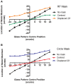
The location (±95% CIs) of the maximum response of the model is plotted as a function of the center of rotation of the 100% coherent, concentric Glass pattern for three conditions in each plot. The mask type varies (A: RF3 and B: circle) and the mask is either centered (green and red) or displaced 20′ (orange and blue). The masks are also detected by the model and provide an anchoring component to the estimated location of maximum response, reducing the rate of change of location as the Glass pattern center position varies and also offsetting the model maximum response towards the center of the mask.
Figure 7
Figure 7
Example stimuli are depicted as described in the text. Judgments were made regarding the center of rotation of the Glass pattern relative to the black outer Gaussian markers.
Figure 8
Figure 8
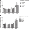
Localization thresholds (+95% CIs) are plotted for each observer in each condition. The addition of a mask (A: RF3 and B: circle) had no consistent impact on localization precision.
Figure 9
Figure 9
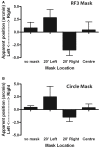
The average perceived shift in Glass pattern center location is plotted (±95% CIs) for the group as a function of masking condition. The means are offset in the opposite direction to the displaced masks although this effect is only significant in the RF3 (A), and not the circle (B), conditions.
Figure 10
Figure 10
(A–C) depict the models response at each radial frequency as a function of signal level. The plots show results for (A) RF3 alone, (B) concentric Glass pattern alone, and (C) an RF3 with a 100% coherent 36 dot-pair concentric Glass pattern superimposed. (D) Shows the change at RF# 3 in (C) when the amplitude is varied with a concentric Glass pattern overlapping (blue) and when a random Glass pattern (black), a 100% coherent radial Glass pattern (red) or no Glass pattern superimposed (as in subplot a). (E) Shows the change in overall response as amplitude varies, quantified as the sum of the squared differences at every RF#, for the same mask conditions.
Figure 11
Figure 11
Example stimuli in which RF deformation must be detected as a function of masking conditions employing no mask, a radial, random, or concentric Glass pattern mask (left to right respectively).
Figure 12
Figure 12
The amplitude required for deformation threshold (+95% CIs) is plotted for each observer with either no mask or a superimposed Glass pattern with radial, concentric, or random structure. Overall the masks were equally effective in reducing performance.

Similar articles

References

    1. Badcock D. R., Clifford C. W. G. (2006). The inputs to global form detection, in Seeing Spatial Form, eds Jenkin M. R. M., Harris L. R. (Oxford: Oxford University Press; ), 43–56
    1. Badcock D. R., Clifford C. W. G., Khuu S. K. (2005). Interactions between luminance and contrast signals in global form detection. Vision Res. 45, 881–889 10.1016/j.visres.2004.09.042 - DOI - PubMed
    1. Badcock D. R., Westheimer G. (1985a). Spatial location and hyperacuity: flank position in the centre and surround zones. Spat. Vis. 1, 3–11 10.1163/156856885X00026 - DOI - PubMed
    1. Badcock D. R., Westheimer G. (1985b). Spatial location and hyperacuity: the centre/surround localization contribution function has two substrates. Vision Res. 25, 1259–1267 10.1016/0042-6989(85)90041-0 - DOI - PubMed
    1. Bell J., Badcock D. R. (2008). Luminance and contrast cues are integrated in global shape detection with contours. Vision Res. 48, 2336–2344 10.1016/j.visres.2008.07.015 - DOI - PubMed

LinkOut - more resources