. 2013 Oct 23;425(20):3875-87.
doi: 10.1016/j.jmb.2013.05.014. Epub 2013 May 23.

In human pseudouridine synthase 1 (hPus1), a C-terminal helical insert blocks tRNA from binding in the same orientation as in the Pus1 bacterial homologue TruA, consistent with their different target selectivities

Affiliations

In human pseudouridine synthase 1 (hPus1), a C-terminal helical insert blocks tRNA from binding in the same orientation as in the Pus1 bacterial homologue TruA, consistent with their different target selectivities

Nadine Czudnochowski et al. J Mol Biol. .

Abstract

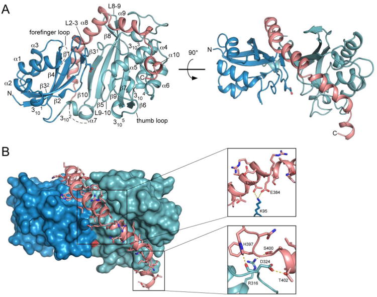
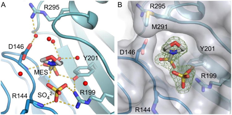
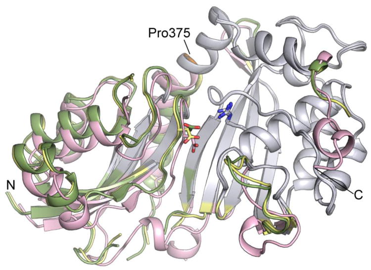
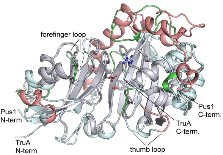
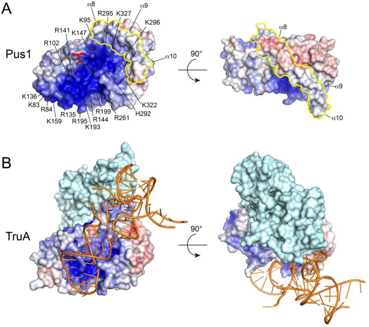
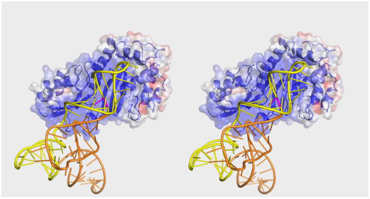
Human pseudouridine (Ψ) synthase Pus1 (hPus1) modifies specific uridine residues in several non-coding RNAs: tRNA, U2 spliceosomal RNA, and steroid receptor activator RNA. We report three structures of the catalytic core domain of hPus1 from two crystal forms, at 1.8Å resolution. The structures are the first of a mammalian Ψ synthase from the set of five Ψ synthase families common to all kingdoms of life. hPus1 adopts a fold similar to bacterial Ψ synthases, with a central antiparallel β-sheet flanked by helices and loops. A flexible hinge at the base of the sheet allows the enzyme to open and close around an electropositive active-site cleft. In one crystal form, a molecule of Mes [2-(N-morpholino)ethane sulfonic acid] mimics the target uridine of an RNA substrate. A positively charged electrostatic surface extends from the active site towards the N-terminus of the catalytic domain, suggesting an extensive binding site specific for target RNAs. Two α-helices C-terminal to the core domain, but unique to hPus1, extend along the back and top of the central β-sheet and form the walls of the RNA binding surface. Docking of tRNA to hPus1 in a productive orientation requires only minor conformational changes to enzyme and tRNA. The docked tRNA is bound by the electropositive surface of the protein employing a completely different binding mode than that seen for the tRNA complex of the Escherichia coli homologue TruA.

Keywords: 2-(N-morpholino)ethane sulfonic acid; FAM; MLASA; Mes; PDB; PEG; Protein Data Bank; RNA-modifying enzyme; SRA; X-ray crystallography; fluorescein amidite; hPus1; human pseudouridine synthase 1; isomerase; mitochondrial myopathy and sideroblastic anemia; polyethylene glycol; pseudouridine; steroid receptor RNA activator; tRNA.


Figures

Figure 1
Figure 1
Overall structure of the Pus1 catalytic domain. (A) Cartoon representation of the Pus1 crystal structure (form II) in two different orientations, rotated by 90°, with the N-terminal domain colored dark-blue and the C-terminal domain colored green. Catalytic Asp146, rendered in ball-and-stick form, is located in the center of the cleft. The C-terminal extension helices α8, α9 and α10 unique to Pus1 are colored salmon (B) Interactions between amino acid residues of helices α8 and α9, with the surface of the Ψ synthase core shown in dark-blue and green. C-terminal helices are colored salmon with amino acid side chains shown as sticks. Pus1 is shown in the same orientation as in Figure 1 A right panel. Right: Close-up views of two main regions of interactions between residues of α8 and α9 with the Ψ synthase core. Hydrogen bonds are depicted as yellow dashes.
Figure 2
Figure 2
Active site cleft and polar contacts between MES, SO42- and water molecules and residues at the active site of Pus1. (A) Active site of crystal form I depicting interactions between MES, SO4 and residues in the active site as yellow dashed lines. Waters lining the cleft are represented as red spheres. (B) Surface representation of Pus1 superimposed on (Fo-Fc) omitmap electron density (4σ) showing the width of the active site cleft. The distance between Cαs of Asp146 and Met291 is about 8 Å.
Figure 3
Figure 3
Conformational changes between Pus1 form I (MES, apo) and form II (apo) crystal structures. The conserved cores of the C-terminal domains of the three Pus1 structures were superposed (colored grey). Form I (MES) is colored in yellow. Form I (apo) in green shows a narrowed active site cleft, and form II (apo) in salmon shows a crystal-form dependent rigid body shift in the N-terminal domain. Catalytic Asp146 and Arg295 are represented as sticks. Pro375 is colored orange. The orientation shown corresponds to the orientation shown in Figure 1 A left panel.
Figure 4
Figure 4
Comparison of the structures of apo-Pus1 (form II) and apo-TruA. Superposition of the apo-Pus1 structure (form II) with the structure of apo-TruA (PDB: 3DJ0) aligned based on the most structurally conserved regions of their common cores, colored grey. Regions of the core not used in the alignment are colored light cyan. Regions outside the core are colored salmon for Pus1 and green for TruA. The five signature Ψ synthase residues, including catalytic Asp, are superimposable, represented as sticks. The orientation shown corresponds to the orientation shown in Figure 1 A left panel.
Figure 5
Figure 5
Electrostatic surface potentials of apo-Pus1 (form II) (A) and TruA from the tRNA-TruA complex (PDB ID: 2NR0) (B). The Pus1 C-terminal insert is colored in yellow. Positive electrostatic potential is colored blue (+10 kT/e), negative electrostatic potential red (-10 kT/e). Electrostatic potentials were calculated with APBS Pus1 and TruA were superposed on their catalytic cores and the two orientations shown correspond to the orientations in Figure 1A. The surface of a dimer of TruA is shown with only one protomer TruA colored according to its electrostatic surface potential and the other protomer colored in light cyan. Bound tRNA is shown in orange cartoon format.
Figure 6
Figure 6
Stereo Plot of tRNAPhe docked to apo-Pus1 (form I). The surface representation of Pus1 is colored according to its electrostatic potential (-5 kT/e to 5 kT/e). tRNAPhe is colored orange with nucleotides corresponding to the Pus1 minimal substrate in yellow. The substrate base is colored purple. The orientation of Pus1 is the same as the orientation of TruA in Figure 5.

References

    1. Charette M, Gray MW. Pseudouridine in RNA: what, where, how, and why. IUBMB Life. 2000;49:341–51. - PubMed
    1. Agris PF. Decoding the genome: a modified view. Nucleic Acids Res. 2004;32:223–38. - PMC - PubMed
    1. Yang C, McPheeters DS, Yu YT. Psi35 in the branch site recognition region of U2 small nuclear RNA is important for pre-mRNA splicing in Saccharomyces cerevisiae. J Biol Chem. 2005;280:6655–62. - PubMed
    1. Yu YT, Shu MD, Steitz JA. Modifications of U2 snRNA are required for snRNP assembly and pre-mRNA splicing. EMBO J. 1998;17:5783–95. - PMC - PubMed
    1. Hamma T, Ferré-D'Amaré AR. Pseudouridine synthases. Chem Biol. 2006;13:1125–35. - PubMed

Publication types