

Gradient biomaterials and their influences on cell migration
- PMID: 23741610
- PMCID: PMC3363018
- DOI: 10.1098/rsfs.2011.0124
Gradient biomaterials and their influences on cell migration
Abstract
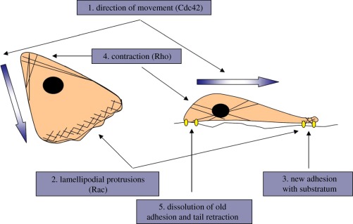
Cell migration participates in a variety of physiological and pathological processes such as embryonic development, cancer metastasis, blood vessel formation and remoulding, tissue regeneration, immune surveillance and inflammation. The cells specifically migrate to destiny sites induced by the gradually varying concentration (gradient) of soluble signal factors and the ligands bound with the extracellular matrix in the body during a wound healing process. Therefore, regulation of the cell migration behaviours is of paramount importance in regenerative medicine. One important way is to create a microenvironment that mimics the in vivo cellular and tissue complexity by incorporating physical, chemical and biological signal gradients into engineered biomaterials. In this review, the gradients existing in vivo and their influences on cell migration are briefly described. Recent developments in the fabrication of gradient biomaterials for controlling cellular behaviours, especially the cell migration, are summarized, highlighting the importance of the intrinsic driving mechanism for tissue regeneration and the design principle of complicated and advanced tissue regenerative materials. The potential uses of the gradient biomaterials in regenerative medicine are introduced. The current and future trends in gradient biomaterials and programmed cell migration in terms of the long-term goals of tissue regeneration are prospected.
Keywords: biointerfaces; biomaterials; cell migration; gradient; regenerative medicine.
Figures
Similar articles
-
Inflammation-mediated matrix remodeling of extracellular matrix-mimicking biomaterials in tissue engineering and regenerative medicine.Acta Biomater. 2022 Oct 1;151:106-117. doi: 10.1016/j.actbio.2022.08.015. Epub 2022 Aug 13. Acta Biomater. 2022. PMID: 35970482 Review.
-
BIOMIMETIC GRADIENT HYDROGELS FOR TISSUE ENGINEERING.Can J Chem Eng. 2010 Dec;88(6):899-911. doi: 10.1002/cjce.20411. Can J Chem Eng. 2010. PMID: 21874065 Free PMC article.
-
Integrative Utilization of Microenvironments, Biomaterials and Computational Techniques for Advanced Tissue Engineering.J Biotechnol. 2015 Oct 20;212:71-89. doi: 10.1016/j.jbiotec.2015.08.005. Epub 2015 Aug 14. J Biotechnol. 2015. PMID: 26281975 Review.
-
Inorganic Biomaterials for Regenerative Medicine.ACS Appl Mater Interfaces. 2020 Feb 5;12(5):5319-5344. doi: 10.1021/acsami.9b17801. Epub 2020 Jan 28. ACS Appl Mater Interfaces. 2020. PMID: 31989815 Review.
-
Engineered biochemical cues of regenerative biomaterials to enhance endogenous stem/progenitor cells (ESPCs)-mediated articular cartilage repair.Bioact Mater. 2023 May 2;26:490-512. doi: 10.1016/j.bioactmat.2023.03.008. eCollection 2023 Aug. Bioact Mater. 2023. PMID: 37304336 Free PMC article. Review.
Cited by
-
Fabrication of transparent hemispherical 3D nanofibrous scaffolds with radially aligned patterns via a novel electrospinning method.Sci Rep. 2018 Feb 21;8(1):3424. doi: 10.1038/s41598-018-21618-0. Sci Rep. 2018. PMID: 29467436 Free PMC article.
-
Investigation of the Viability, Adhesion, and Migration of Human Fibroblasts in a Hyaluronic Acid/Gelatin Microgel-Reinforced Composite Hydrogel for Vocal Fold Tissue Regeneration.Adv Healthc Mater. 2016 Jan 21;5(2):255-65. doi: 10.1002/adhm.201500370. Epub 2015 Oct 26. Adv Healthc Mater. 2016. PMID: 26501384 Free PMC article.
-
Functionally graded biomaterials for use as model systems and replacement tissues.Adv Funct Mater. 2020 Oct 28;30(44):1909089. doi: 10.1002/adfm.201909089. Epub 2020 Mar 4. Adv Funct Mater. 2020. PMID: 33456431 Free PMC article.
-
Time-dependent migratory behaviors in the long-term studies of fibroblast durotaxis on a hydrogel substrate fabricated with a soft band.Langmuir. 2014 Jun 3;30(21):6187-96. doi: 10.1021/la501058j. Epub 2014 May 22. Langmuir. 2014. PMID: 24851722 Free PMC article.
-
Polycaprolactone Fiber and Laminin and Collagen IV Protein Incorporation in Implants Enhances Wound Healing in a Novel Mouse Skin Splint Model.J Tissue Eng Regen Med. 2024 Sep 4;2024:2515383. doi: 10.1155/2024/2515383. eCollection 2024. J Tissue Eng Regen Med. 2024. PMID: 40225757 Free PMC article.
References
-
- Godwin J. W., Brockes J. P. 2006. Regeneration, tissue injury and the immune response. J. Anat. 209, 423–43210.1111/j.1469-7580.2006.00626.x (doi:10.1111/j.1469-7580.2006.00626.x) - DOI - DOI - PMC - PubMed
-
- Jagur-Grodzinski J. 2006. Polymers for tissue engineering, medical devices, and regenerative medicine. Concise general review of recent studies. Polym. Adv. Technol. 17, 395–41810.1002/pat.729 (doi:10.1002/pat.729) - DOI - DOI
-
- Redd M. J., Kelly G., Dunn G., Way M., Martin P. 2006. Imaging macrophage chemotaxis in vivo: studies of microtubule function in zebrafish wound inflammation. Cell Motil. Cytoskeleton 63, 415–42210.1002/cm.20133 (doi:10.1002/cm.20133) - DOI - DOI - PubMed
-
- Cara D. C., Kaur J., Forster M., McCafferty D. M., Kubes P. 2001. Role of P38 mitogen-activated protein kinase in chemokine-induced emigration and chemotaxis in vivo. J. Immunol. 167, 6552–6558 - PubMed
-
- Ramón Y., Cajal S. 1892. La retine de vertebres. La Cellule 9, 119–258
LinkOut - more resources
Full Text Sources
Other Literature Sources
