. 2013 Sep;21(5):840-8.
doi: 10.1109/TNSRE.2013.2264920. Epub 2013 Jun 4.

Stability radius as a method for comparing the dynamics of neuromechanical systems

Stability radius as a method for comparing the dynamics of neuromechanical systems

Jeffrey T Bingham et al. IEEE Trans Neural Syst Rehabil Eng. 2013 Sep.

Abstract

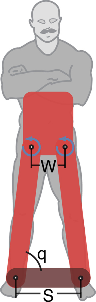
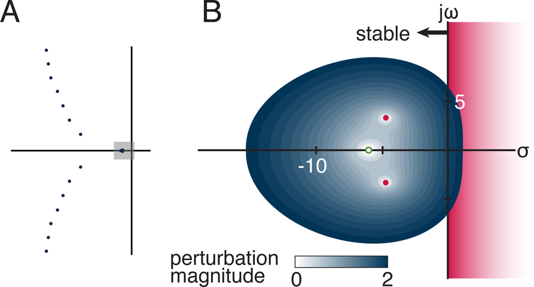
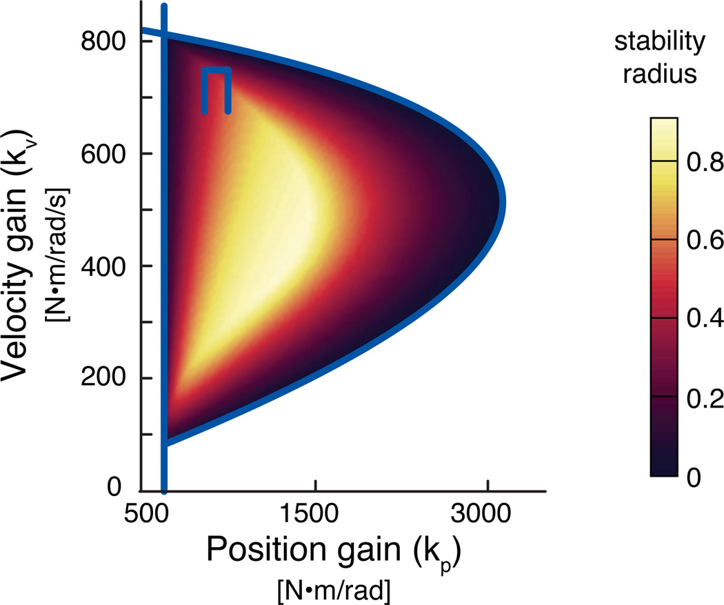
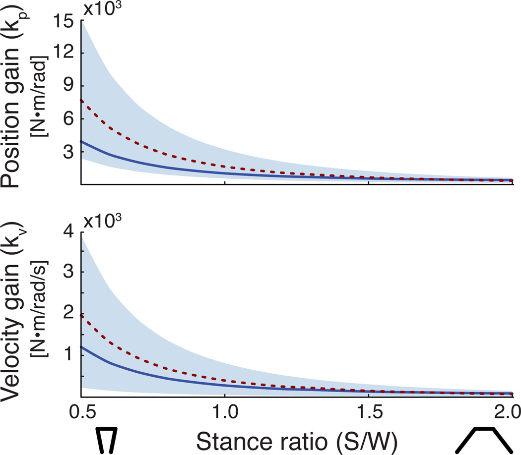
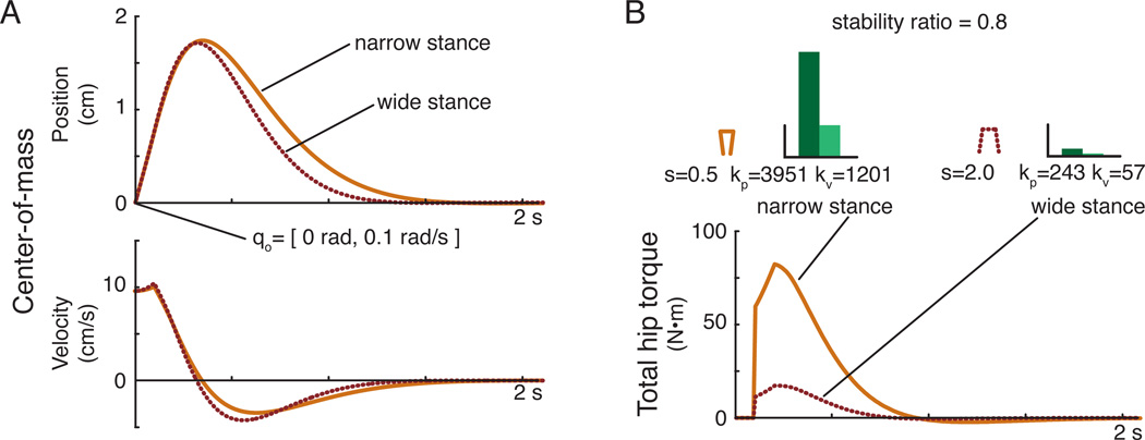
Robust motor behaviors emerge from neuromechanical interactions that are nonlinear, have delays, and contain redundant neural and biomechanical components. For example, in standing balance a subject's muscle activity (neural control) decreases as stance width (biomechanics) increases when responding to a lateral perturbation, yet the center-of-mass motion (behavior) is nearly identical regardless of stance width. We present stability radius, a technique from robust control theory, to overcome the limitations of classical stability analysis tools, such as gain margin, which are insufficient for predicting how concurrent changes in both biomechanics (plant) and neural control (controller) affect system behavior. We first present the theory and then an application to a neuromechanical model of frontal-plane standing balance with delayed feedback. We show that stability radius can quantify differences in the sensitivity of system behavior to parameter changes, and predict that narrowing stance width increases system robustness. We further demonstrate that selecting combinations of stance width (biomechanics) and feedback gains (neural control) that have the same stability radius produce similar center-of-mass behavior in simulation. Therefore, stability radius may provide a useful tool for understanding neuromechanical interactions in movement and could aid in the design of devices and therapies for improving motor function.


Figures

Figure 1
Figure 1
Frontal-plane model of human mediolateral balance control. Frontal-plane motion of the body was modeled as a four-bar linkage. Two bars represented the legs, the third bar was the torso, and the fourth bar was the ground. Perturbations were applied as initial conditions in lieu of ground translations. Important parameters of the model were the hip width (W), stance width (S), and ankle angle (q).
Figure 2
Figure 2
Eigenvalues and pseudospectra for a single feedback gain pair at the nominal stance width. (A) A subset of the infinite number of eigenvalues for the delayed four-bar linkage model (S/W=2, kp=243 N-m/rad, and kv=57 N-m/rad/s). Shaded box is complex region surrounding the three dominant eigenvalues and enlarged in (B) The pseudospectra corresponding to a perturbation that caused the eigenvalues to go unstable is represented by dotted lines. The value of the smallest perturbation to cause any of the eigenvalues to go unstable was the stability radius for this system. For the neuromechanical system modeled here, the more negative eigenvalue (unfilled dot) went unstable at a lower level of perturbation than the dominant eigenvalues that were closer to the imaginary axis (filled dots).
Figure 3
Figure 3
Stability radius across all stable feedback gains at the nominal stance width. The solid lines giving a D-shaped boundary encloses the range of all stable feedback gains at the nominal stance width (S/W=1.0). Shaded intensity represents the value of the stability radius for each stable gain pair. Lighter values have greater stability radius and resulted in system behavior that was less sensitive to parameter variations.
Figure 4
Figure 4
Stable feedback gains across stance width. The shaded regions defined all stable feedback gains across stance widths. The dotted line indicates the feedback gain pairs that produced maximum stability radius across stance widths. The solid line indicates the feedback gain values that produced the same stability radius (r=0.8) across stance widths.
Figure 5
Figure 5
Simulated center-of-mass position across stance widths using feedback gains that produce the same stability radius. (A) Although feedback gain values differed substantially across stance widths, the resulting center-of-mass motion produced in response to a change in the initial state of the system was similar in narrow (solid) and wide (dotted) stance widths when feedback gains with the same stability radius were used. (B) The resulting torque necessary to generate the center-of-mass response was an order of magnitude smaller for the wide stance compared to the narrow stance.

References

    1. Dorf RC, Bishop RH. Modern Control Systems, 9th ed. plus 0.5em minus 0.4em. Upper Saddle River, NJ: Prentice-Hall; 2000.
    1. Hinrichsen D, Pritchard A. Mathematical Systems Theory I: Modelling State Space Analysis, Stability and Robustness, 2nd ed. plus 0.5em minus 0.4em. Berlin, Heidelberg: Springer Verlag; 2005.
    1. Trefethen LN, Embree M. Spectra and Pseudospectra: The Behavior of Nonnormal Matrices and Operators. plus 0.5em minus 0.4em. Princeton, NJ: Princeton University Press; 2005.
    1. Hinrichsen D, Pritchard A. Stability radii of linear systems. Systems & Control Letters. 1986 Feb;7(1):1–10.
    1. Martin J. State-space measures for stability robustness. IEEE Transactions on Automatic Control. 1987 Jun;32(6):509–512.

Publication types