

doi: 10.1364/BOE.4.000831.
Print 2013 Jun 1.
Simultaneous spatial and temporal focusing for tissue ablation
Affiliations
- PMID: 23761847
- PMCID: PMC3675863
- DOI: 10.1364/BOE.4.000831
Item in Clipboard
Simultaneous spatial and temporal focusing for tissue ablation
Biomed Opt Express.
.
Abstract
Simultaneous spatial temporal focusing (SSTF) is used to deliver microjoule femtosecond pulses with low numerical aperture geometries (<0.05 NA) with characteristics that are significantly improved compared to standard focusing paradigms. Nonlinear effects that would normally result in focal plane shifts and focal spot distortion are mitigated when SSTF is employed. As a result, it is shown that SSTF will enable surgical implementations that are presently inhibited.
Keywords: (140.3390) Laser materials processing; (190.4360) Nonlinear optics, devices.
Figures
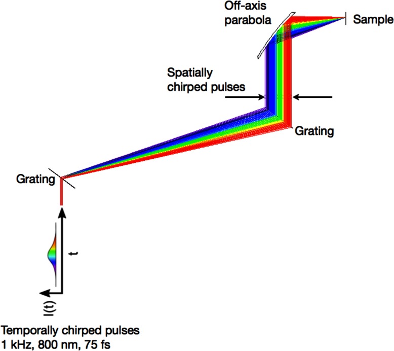
The simultaneous spatial temporal focusing geometry.
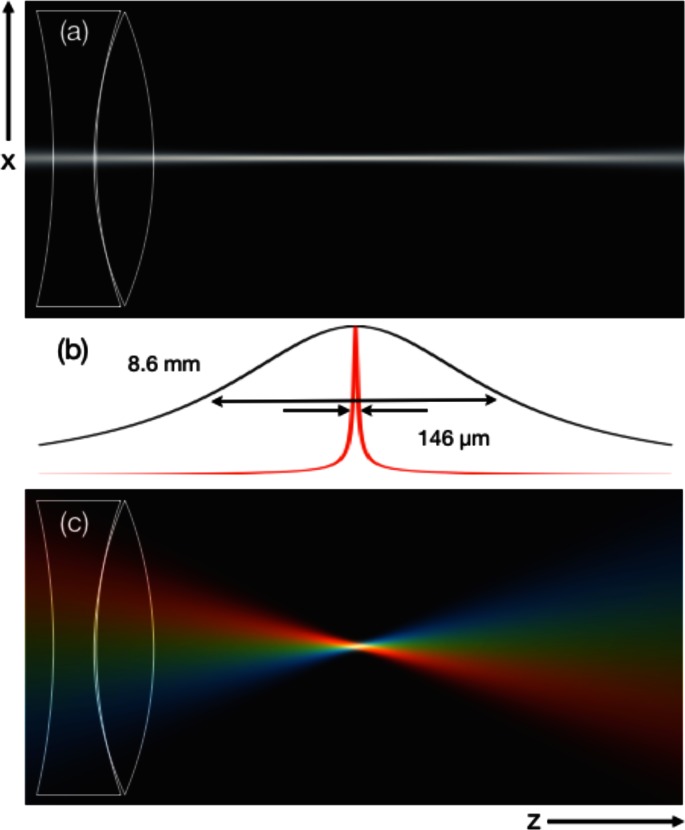
(a) Intensity profile of a beam focused to a 33 µm spot size (1/e2 beam diameter) using a standard focal geometry. (b) Integrated intensity contours along the axial dimension of the focus without SSTF (black) and with SSTF (red). (c) Intensity profile of a beam with an SSTF focusing geometry also focused to a 33 µm spot size. The beam aspect ratio, , is 11.
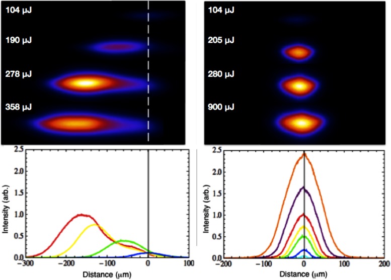
Image of focus as a function of pulse energy for a standard focal geometry (left) and an SSTF focal geometry (right). The dashed line in the left panel indicates the focal plane of the focusing optic. The beam’s focal position shifts toward this focusing optic as the energy is increased.
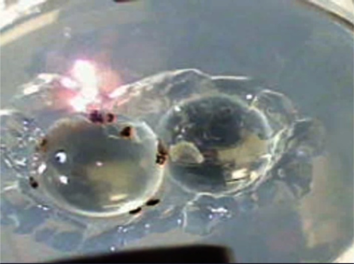
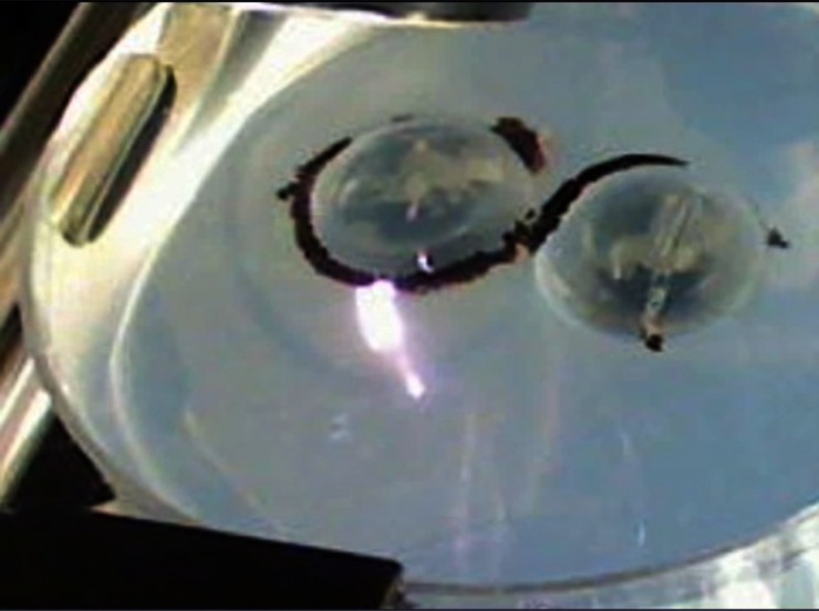
Single-frame excerpt from a video recording of laser ablation on the surface of a porcine lens mounted in agarose using a standard focusing geometry (Media 1 , 685 KB). Two lenses are shown; however, only the lens on the left is being ablated.
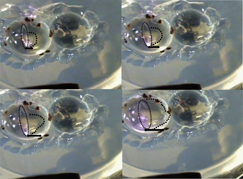
Montage that details the propagation of the bubbles that follow the first cut with the standard focusing geometry.
Single-frame excerpt from a video recording of channels cut across the surface of a porcine lens mounted in agarose, using a SSTF focusing geometry (Media 2 , 731 KB).
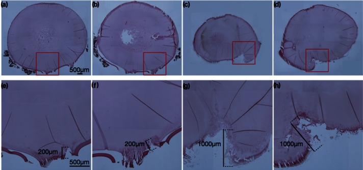
Histological tissue slices of the laser-treated porcine lens. Panels (a), (b), (e), (f), are for SSTF focusing; panels (c), (d), (g), (h) are with a standard focus. The black scale bars shown in (a) and (e) are 500 µm, and the same scaling is used for all images within each row. Additional scale bars in (e)-(h) highlight the depth of laser modification in each case, ~200 um for (e), (f) and ~1 mm for (g), (h).
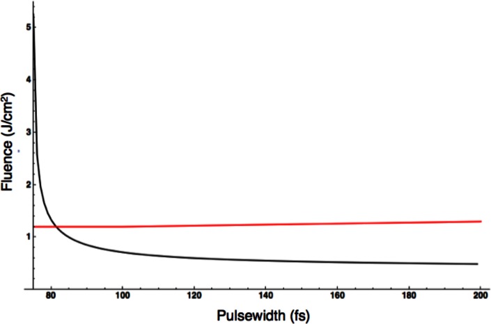
Fluence as a function of laser pulse duration for the SSTF focus used in the eye ablation experiments. The black line is the fluence of the focus. The red line is the ablation threshold fluence as taken from reference [14]. There is a slight positive slope to the red ablation fluence line.
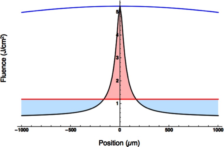
Fluence as a function of axial position. Blue – is the fluence for the standard focus. Black - is the fluence for the SSTF focus. Red – is the measured ablation threshold (from [14]) for a 100 fs pulse. The light red fill illustrates the portion of the SSTF focus that is above the ablation threshold and the region were damage could be expected. The light blue fill illustrates the region of the SSTF focus below the ablation threshold. Note that the standard focus (blue contour) is above the ablation threshold (red contour) for the entire region depicted in the plot.
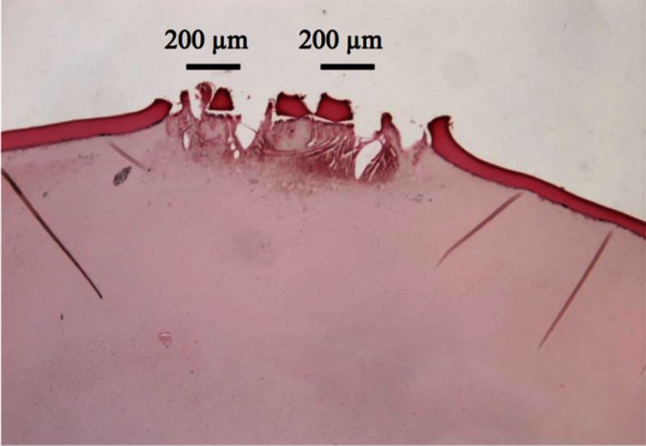
Histological tissue slice of porcine lens. SSTF was employed and the sample was translated at a speed of 10.8 mm/s through focus.
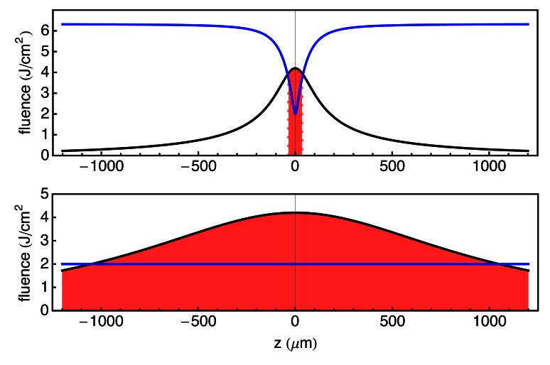
Upper plot – SSTF fluence (black curve), blue is ablation threshold assuming a square root dependence on the ablation threshold. Red filling is region where the pulse fluence is above damage threshold. Lower plot – Standard focus fluence (black curve), blue is ablation threshold for a constant pulsewidth. Red filling is region where the pulse fluence is above damage threshold.
References
-
- Pronko P., Dutta S., Squier J., Rudd V., Du D., Mourou G., “Machining of submicron holes using a femtosecond laser at 800 nm,” Opt. Commun. 114(1-2), 106–110 (1995). 10.1016/0030-4018(94)00585-I - DOI
-
- Juhasz T., Kastis G. A., Suárez C., Bor Z., Bron W. E., “Time-resolved observations of shock waves and cavitation bubbles generated by femtosecond laser pulses in corneal tissue and water,” Lasers Surg. Med. 19(1), 23–31 (1996). 10.1002/(SICI)1096-9101(1996)19:1<23::AID-LSM4>3.0.CO;2-S - DOI - PubMed
-
- Juhasz T., Loesel F. H., Kurtz R. M., Horvath C., Bille J. F., Mourou G., “Corneal refractive surgery with femtosecond lasers,” IEEE J. Sel. Top. Quantum Electron. 5(4), 902–910 (1999). 10.1109/2944.796309 - DOI
-
- Kurtz R. M., Horvath C., Liu H. H., Krueger R. R., Juhasz T., “Lamellar refractive surgery with scanned intrastromal picosecond and femtosecond laser pulses in animal eyes,” J. Refract. Surg. 14(5), 541–548 (1998). - PubMed
Grants and funding
LinkOut - more resources
Full Text Sources
Other Literature Sources
Research Materials