. 2013 Jun 5;78(5):758-72.
doi: 10.1016/j.neuron.2013.05.030.

Impact of neuronal properties on network coding: roles of spike initiation dynamics and robust synchrony transfer

Affiliations

Impact of neuronal properties on network coding: roles of spike initiation dynamics and robust synchrony transfer

Stéphanie Ratté et al. Neuron. .

Abstract

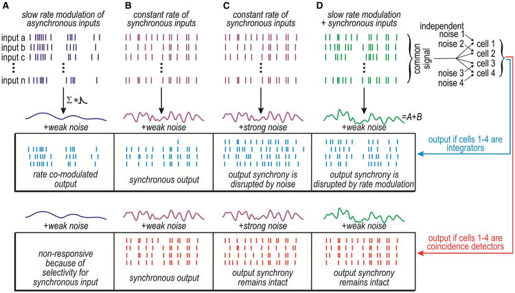
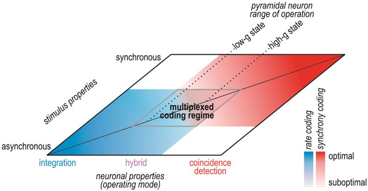
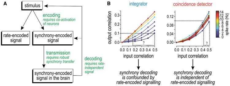
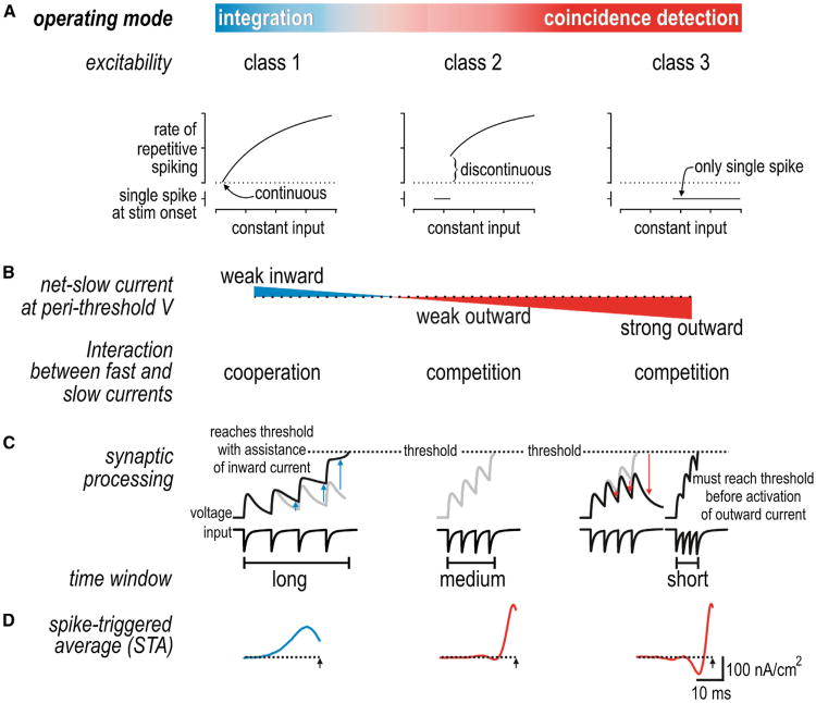
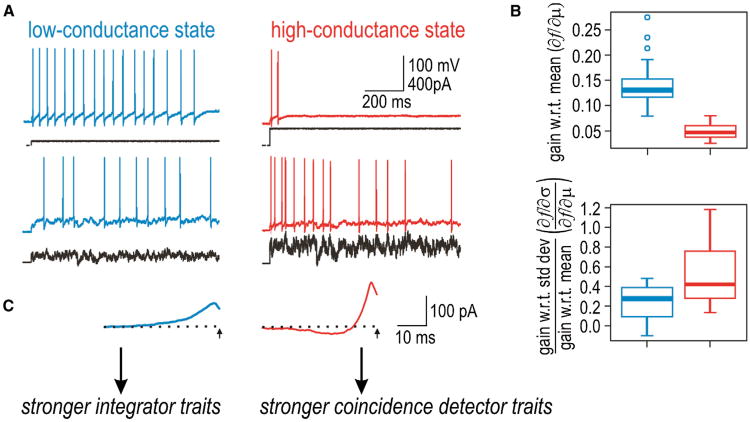
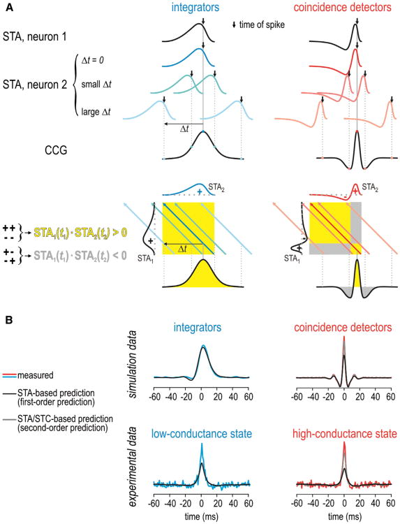
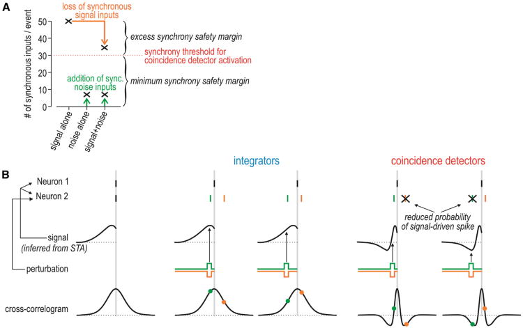
Neural networks are more than the sum of their parts, but the properties of those parts are nonetheless important. For instance, neuronal properties affect the degree to which neurons receiving common input will spike synchronously, and whether that synchrony will propagate through the network. Stimulus-evoked synchrony can help or hinder network coding depending on the type of code. In this Perspective, we describe how spike initiation dynamics influence neuronal input-output properties, how those properties affect synchronization, and how synchronization affects network coding. We propose that synchronous and asynchronous spiking can be used to multiplex temporal (synchrony) and rate coding and discuss how pyramidal neurons would be well suited for that task.


Figures

Figure 1
Figure 1. Synchrony Transfer Differs between Operating Modes
Top: the generation of differently shaped cumulative inputs based on the summation of input spike trains convolved with a synaptic conductance waveform. Stimulus and/or noise conditions differ between (A)–(D). Bottom: responses within a set of integrators or coincidence detectors receiving common (shared) input and independent noise. Unlike integrators, coincidence detectors respond selectively to synchronous input (compare A and B). Both integrators and coincidence detectors receiving common synchronous input will spike synchronously (B), but synchrony transfer is more robust among coincidence detectors, i.e., their output synchrony is less easily disrupted by strong independent noise (C) or by rate-modulated input (D). The robustness of synchrony transfer is a distinguishing feature of coincidence detectors.
Figure 2
Figure 2. Neural Coding Depends Jointly on Neuronal Operating Mode and Stimulus Properties
Neuronal operating mode is represented as a continuum on one axis. Pyramidal neurons tend to operate in the middle range and can shift where they operate based on factors like conductance state. Input synchrony is represented on the other axis. Neural coding strategies are represented in blue (rate coding) and red (synchrony coding), and deeper colors represent better coding than paler colors. Pale regions overlap, revealing a regime in which a hybrid operating mode and multiplexed coding are possible.
Figure 3
Figure 3. Requirements for Synchrony Coding and the Robustness of Synchrony Transfer to Spike-Rate Variation
(A) A synchrony-encoded signal arises from stimulus-dependent coactivation of neurons, which is not mutually exclusive of rate-encoded signaling. For synchrony-encoded signals to reach the CNS, they mustbe reliably transmitted across multiple synapses and must remain decodableinorder toprovide information about the original stimulus. Decodability relies on robust synchrony transfer. (B) Graphs illustrate the challenge of decoding synchrony. Among integrators, the correlation input-output relationship varies with spike rate; consequently, for a given output correlation value, one cannot infer (decode) the input correlation without also knowing the spike rate. This suggests that synchrony coding cannot operate independently of rate coding and would necessitate a complicated decoding mechanism. However, among coincidence detectors, the input-output relationship is not confounded by variations in spike rate, meaning synchrony decoding from coincidence detectors is straightforward. (B) is modified from Hong et al. (2012).
Figure 4
Figure 4. Spike Initiation Dynamics Control Operating Mode
(A) Classes 1, 2, and 3 of excitability are distinguished by the shape of the frequency-current curve defined by constant stimulation. Class 3 neurons (and class 2 neurons within a certain stimulus range) fire only one or a few spikes at stimulus onset. Those properties emerge from distinct nonlinear dynamical mechanisms that reflect whether fast and slow currents cooperate or compete during spike initiation. (B) Differences in spike initiation dynamics can be ascribed to differences in the direction and magnitude of the net-slow current active at perithreshold potentials. (C) Inward current helps sustain the depolarization caused by excitatory synaptic inputs, thereby lengthening the integration time window; outward current truncates depolarization, thereby shortening the integration time window. (D) Differential processing is also evident in the shape of the spike-triggered stimulus average (STA).
Figure 5
Figure 5. Pyramidal Neuron Operating Mode Is Intermediate and Modulable
(A) When tested in a low-conductance state, CA1 pyramidal neurons spike repetitively to constant stimulation and can maintain low spike rates, consistent with class 1 excitability. When the same neuron is tested in the high-conductance state (recreated via dynamic clamp), excitability is shifted toward class 2 excitability, as evidenced by a reduced tendency to maintain repetitive spiking during constant stimulation. Fluctuating stimuli can elicit vigorous spiking in either conductance state. (B) The shift in excitability is accompanied by a shift in coding properties: neurons become less sensitive to the mean stimulus intensity (m) and relatively more sensitive to the amplitude of stimulus fluctuations (s), consistent with coincidence detector traits becoming more prominent in the high-conductance state. (C) The shift is also accompanied by reshaping of the STA from a broad monophasic form to a narrower biphasic form. Modified from Hong et al. (2012).
Figure 6
Figure 6. Predicting the Cross-Correlogram
(A) The cross-correlogram (CCG) can be predicted by convolving the STAs of each neuron. Top: the STA in neuron 2 shifted by different Δt relative to the STA in neuron 1. For Δt = 0, the two STAs overlap perfectly, which corresponds to a high cross-correlation value. For large Δt, the cross-correlation drops to 0 as the STAs no longer overlap. For coincidence detectors, the cross-correlation can be negative for intermediate Δt if the STAs line up out of phase. Bottom: another depiction in which the STA in neuron 1 (STA1) is plotted against the STA in neuron 2 (STA2). Shading represents STA1(t1)·STA2(t2) with yellow corresponding to conditions in which the positive and negative components of STA1 are in phase with the positive and negative components of STA2, and gray corresponding to conditions in which those components are out of phase. Colored arrows are the projections of STA2 across STA1(t1)·STA2(t2) for the same Δt values shown in the top panel. The total cross-correlation represents the sum of STA1(t1)·STA2(t2) across that arrow. (B) Examples of predicted CCGs for comparison with measured CCGs. The first-order prediction (based on the STA alone) provides a satisfactory fit to CCGs measured in the integrator model but does a poor job fitting the peak of CCGs measured from coincidence detector models. The “excess” synchrony was better accounted for by the second-order prediction (based on the STA and STC). For experimental data from CA1 pyramidal neurons, the second-order prediction becomes relatively more important when neurons are shifted toward the coincidence detector mode (i.e., in the high-conductance state) but is relevant even in the low-conductance state insofar as the first-order prediction is imperfect. This is consistent with pyramidal neurons operating inthe middlerange of the operating mode continuum.
Figure 7
Figure 7. Robustness of Synchrony Transfer to Noise
(A) Graph depicts synchronous input to a hypothetical postsynaptic coincidence detector that requires 30 synchronous inputs for activation. Without noise, the signal coactivates 50 presynaptic neurons. This means that up to 20 synchronous inputs could fail to occur (e.g., because of the effects of noise) without compromising activation of the postsynaptic neuron—this constitutes the excess synchrony safety margin. On the other hand, noise would have to coactivate at least 30 presynaptic neurons in order to activate the postsynaptic neuron, which is unlikely—this constitutes the minimum synchrony safety margin. The former safety margin reduces false negatives, whereas the latter reduces false positives with respect to correctly detecting the input signal. Integrators, by definition, have a lower synchrony threshold, which implies a smaller minimum synchrony safety margin. (B) If two neurons spike more synchronously than expected by chance, they probably receive common input (signal) and we can infer the shape of that input based on the STA. Furthermore, if one neuron spikes, the CCG tells us the probability that the other neuron will spike. If neuron 2 receives a brief perturbation, its spike (shown in the same color as the perturbation) is jittered relative to the spike in the other neuron. In an integrator, because the CCG peak is so broad, a jittered spike will still tend to fall near the peak of the CCG (as shown by colored dots). In a coincidence detector, by comparison, even moderate jittering can shift the timing of the anticipated spike such that it coincides with one of the troughs surrounding the narrow peak of the multiphasic CCG, which implies that the probability of spiking falls to below-chance levels and that the spike will probably be “lost.” Thus, the spike initiation dynamics that are characteristic of coincidence detectors implement a quality control mechanism, wherein precision is maintained at the expense of reliability. The CCG troughs also ensure that tightly synchronized spikes are clearly distinguishable from asynchronous spikes because the probability of loosely synchronized spiking is very low.
Figure 8
Figure 8. Multiplexed Coding
Top rasters depict input comprising synchronous inputs plus rate-modulated asynchronous inputs. Bottom rasters depict output spike trains in four postsynaptic neurons operating in hybrid mode. Synchronous inputs elicit synchronous output spikes (purple), whereas rate-modulated asynchronous inputs elicit rate-modulated asynchronous output spikes (blue). By comparison, pure coincidence detectors would not respond to the asynchronous inputs (see Figure 1A) and pure integrators would not respond synchronously to synchronous inputs because of their rate-modulated asynchronous spiking (see Figure 1D).

References

    1. Abeles M. Role of the cortical neuron: integrator or coincidence detector? Isr J Med Sci. 1982;18:83–92. - PubMed
    1. Agüera y Arcas B, Fairhall AL. What causes a neuron to spike? Neural Comput. 2003;15:1789–1807. - PubMed
    1. Agüera y Arcas B, Fairhall AL, Bialek W. Computation in a single neuron: Hodgkin and Huxley revisited. Neural Comput. 2003;15:1715–1749. - PubMed
    1. Alonso JM, Usrey WM, Reid RC. Precisely correlated firing in cells of the lateral geniculate nucleus. Nature. 1996;383:815–819. - PubMed
    1. Arsiero M, Lüscher HR, Lundstrom BN, Giugliano M. The impact of input fluctuations on the frequency-current relationships of layer 5 pyramidal neurons in the rat medial prefrontal cortex. J Neurosci. 2007;27:3274–3284. - PMC - PubMed

Publication types

LinkOut - more resources