Microstructural Observation with MicroCT and Histological Analysis of Human Alveolar Bone Biopsy from a Planned Implant Site: A Case Report
- PMID: 23802023
- PMCID: PMC3680989
- DOI: 10.2174/1874210601307010047
Microstructural Observation with MicroCT and Histological Analysis of Human Alveolar Bone Biopsy from a Planned Implant Site: A Case Report
Abstract
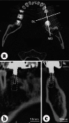
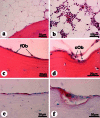
The subject was a 53-year-old male. An alveolar bone sample was obtained from the site of the lower left first molar, before dental implant placement. Although the details of the trabecular structure were not visible with conventional computed tomography, micro-computed tomography (microCT) three-dimensional images of the alveolar bone biopsy sample showed several plate-like trabeculae extending from the lingual cortical bone. Histological observations of the bone sample revealed trabeculae, cuboidal osteoblasts, osteoclasts and hematopoietic cells existing in the bone tissue at the implantation site. Bone metabolic markers and calcaneal bone density were all within normal ranges, indicating no acceleration of the patient's bone metabolism. Using microCT, and histological and histomorphometrical techniques, a great deal of valuable information about the bone tissue was obtained from a biopsy sample extracted from the patient's planned implant site.
Keywords: Bone biopsy; bone micro-structure; dental implant; histomorphometry; human alveolar bone; microCT..
Figures


Similar articles
-
Stereological measures of trabecular bone structure: comparison of 3D micro computed tomography with 2D histological sections in human proximal tibial bone biopsies.J Microsc. 2005 May;218(Pt 2):171-9. doi: 10.1111/j.1365-2818.2005.01469.x. J Microsc. 2005. PMID: 15857378
-
The reliability of cone-beam computed tomography to assess bone density at dental implant recipient sites: a histomorphometric analysis by micro-CT.Clin Oral Implants Res. 2013 Aug;24(8):871-9. doi: 10.1111/j.1600-0501.2011.02390.x. Epub 2012 Jan 17. Clin Oral Implants Res. 2013. PMID: 22250839
-
The Specific Morphological Features of Alveolar Bone.J Craniofac Surg. 2018 Jul;29(5):1216-1219. doi: 10.1097/SCS.0000000000004395. J Craniofac Surg. 2018. PMID: 29498973
-
Utilizing micro-computed tomography to evaluate bone structure surrounding dental implants: a comparison with histomorphometry.J Biomed Mater Res B Appl Biomater. 2013 Oct;101(7):1259-66. doi: 10.1002/jbm.b.32938. Epub 2013 May 10. J Biomed Mater Res B Appl Biomater. 2013. PMID: 23661363
-
The skeleton in primary hyperparathyroidism: a review focusing on bone remodeling, structure, mass, and fracture.APMIS Suppl. 2001;(102):1-52. APMIS Suppl. 2001. PMID: 11419022 Review.
Cited by
-
Effects of local melatonin application on post-extraction sockets after third molar surgery. A pilot study.Med Oral Patol Oral Cir Bucal. 2014 Nov 1;19(6):e628-33. doi: 10.4317/medoral.19851. Med Oral Patol Oral Cir Bucal. 2014. PMID: 25350595 Free PMC article. Clinical Trial.
References
-
- Jaffin RA, Berman CL. The excessive loss of Branemark fixtures in type IV bone: a 5-year analysis. J Periodontol. 1991;62:2–4. - PubMed
-
- Herrmann I, Lekholm U, Holm S, Kultje C. Evaluation of patient and implant characteristics as potential prognostic factors for oral implant failures. Int J Oral Maxillofac Implants. 2005;20:220–30. - PubMed
-
- Malik R, Garg R, Suresh DK, Chandna S. Success or failure of a dental implant: its relationship to bone density: a case report of a failed implant. J Contemp Dent Pract. 2010;11:E065–72. - PubMed
-
- Lekholm U, Zarb G. Patient selection and preparation. Tissue-integrated prostheses: Osseointegration in clinical dentistry. Chicago: Quintessence Publishing; 1985. pp. 199–209.
-
- Yim JH, Ryu DM, Lee BS, Kwon YD. Analysis of digitalized panorama and cone beam computed tomographic image distortion for the diagnosis of dental implant surgery. J Craniofac Surg. 2011;22:669–73. - PubMed
LinkOut - more resources
Full Text Sources
Other Literature Sources
