

A patient-specific study of type-B aortic dissection: evaluation of true-false lumen blood exchange
- PMID: 23829346
- PMCID: PMC3734007
- DOI: 10.1186/1475-925X-12-65
A patient-specific study of type-B aortic dissection: evaluation of true-false lumen blood exchange
Abstract
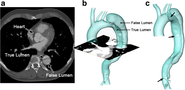
Background: Aortic dissection is a severe pathological condition in which blood penetrates between layers of the aortic wall and creates a duplicate channel - the false lumen. This considerable change on the aortic morphology alters hemodynamic features dramatically and, in the case of rupture, induces markedly high rates of morbidity and mortality.
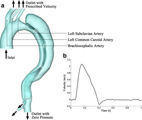
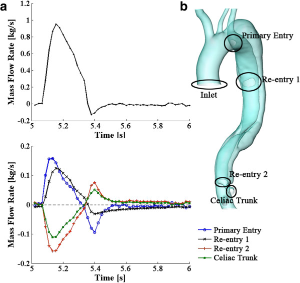
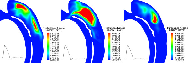
Methods: In this study, we establish a patient-specific computational model and simulate the pulsatile blood flow within the dissected aorta. The k-ω SST turbulence model is employed to represent the flow and finite volume method is applied for numerical solutions. Our emphasis is on flow exchange between true and false lumen during the cardiac cycle and on quantifying the flow across specific passages. Loading distributions including pressure and wall shear stress have also been investigated and results of direct simulations are compared with solutions employing appropriate turbulence models.
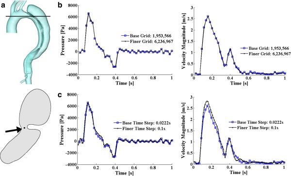
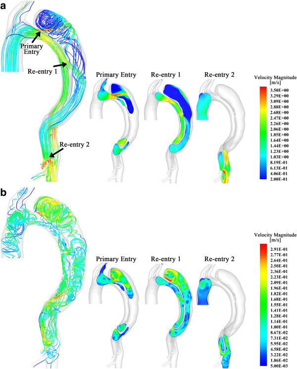
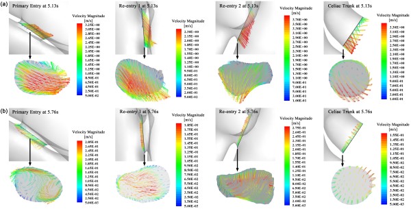
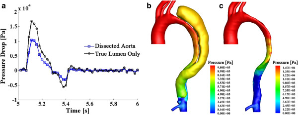
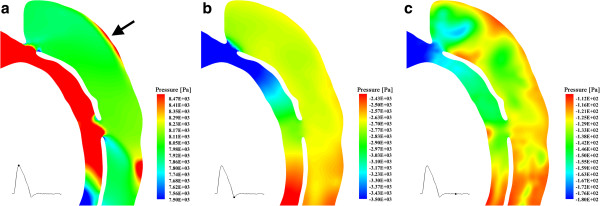
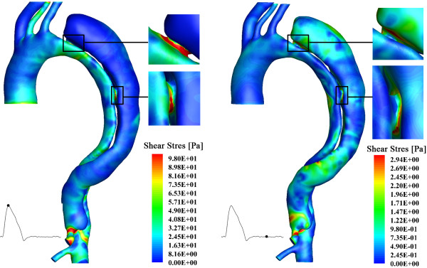
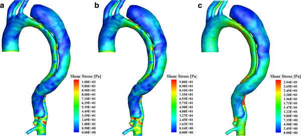
Results: Our results indicate that (i) high velocities occur at the periphery of the entries; (ii) for the case studied, approximately 40% of the blood flow passes the false lumen during a heartbeat cycle; (iii) higher pressures are found at the outer wall of the dissection, which may induce further dilation of the pseudo-lumen; (iv) highest wall shear stresses occur around the entries, perhaps indicating the vulnerability of this region to further splitting; and (v) laminar simulations with adequately fine mesh resolutions, especially refined near the walls, can capture similar flow patterns to the (coarser mesh) turbulent results, although the absolute magnitudes computed are in general smaller.
Conclusions: The patient-specific model of aortic dissection provides detailed flow information of blood transport within the true and false lumen and quantifies the loading distributions over the aorta and dissection walls. This contributes to evaluating potential thrombotic behavior in the false lumen and is pivotal in guiding endovascular intervention. Moreover, as a computational study, mesh requirements to successfully evaluate the hemodynamic parameters have been proposed.
Figures
Similar articles
-
Three-dimensional modelling and hemodynamic simulation of the closure of multiple entry tears in type B aortic dissection.Med Phys. 2024 Jan;51(1):42-53. doi: 10.1002/mp.16852. Epub 2023 Dec 1. Med Phys. 2024. PMID: 38038366
-
The risk of stanford type-A aortic dissection with different tear size and location: a numerical study.Biomed Eng Online. 2016 Dec 28;15(Suppl 2):128. doi: 10.1186/s12938-016-0258-y. Biomed Eng Online. 2016. PMID: 28155679 Free PMC article.
-
Analysis of flow patterns in a patient-specific aortic dissection model.J Biomech Eng. 2010 May;132(5):051007. doi: 10.1115/1.4000964. J Biomech Eng. 2010. PMID: 20459208
-
A perspective review on numerical simulations of hemodynamics in aortic dissection.ScientificWorldJournal. 2014 Feb 3;2014:652520. doi: 10.1155/2014/652520. eCollection 2014. ScientificWorldJournal. 2014. PMID: 24672348 Free PMC article. Review.
-
Predictive Methods for Thrombus Formation in the Treatment of Aortic Dissection and Cerebral Aneurysms: A Comprehensive Review.Bioengineering (Basel). 2024 Aug 28;11(9):871. doi: 10.3390/bioengineering11090871. Bioengineering (Basel). 2024. PMID: 39329613 Free PMC article. Review.
Cited by
-
The Influence of Minor Aortic Branches in Patient-Specific Flow Simulations of Type-B Aortic Dissection.Ann Biomed Eng. 2023 Jul;51(7):1627-1644. doi: 10.1007/s10439-023-03175-4. Epub 2023 Mar 26. Ann Biomed Eng. 2023. PMID: 36967447 Free PMC article.
-
Multilayer flow modulator enhances vital organ perfusion in patients with type B aortic dissection.Am J Physiol Heart Circ Physiol. 2018 Nov 1;315(5):H1182-H1193. doi: 10.1152/ajpheart.00199.2018. Epub 2018 Aug 10. Am J Physiol Heart Circ Physiol. 2018. PMID: 30095992 Free PMC article.
-
An in vitro Assessment of the Haemodynamic Features Occurring Within the True and False Lumens Separated by a Dissection Flap for a Patient-Specific Type B Aortic Dissection.Front Cardiovasc Med. 2022 Mar 17;9:797829. doi: 10.3389/fcvm.2022.797829. eCollection 2022. Front Cardiovasc Med. 2022. PMID: 35369331 Free PMC article.
-
Mathematical modeling and numerical simulation of arterial dissection based on a novel surgeon's view.Biomech Model Mechanobiol. 2023 Dec;22(6):2097-2116. doi: 10.1007/s10237-023-01753-y. Epub 2023 Aug 8. Biomech Model Mechanobiol. 2023. PMID: 37552344 Free PMC article.
-
The Necessity to Seal the Re-Entry Tears of Aortic Dissection After TEVAR: A Hemodynamic Indicator.Front Bioeng Biotechnol. 2022 Mar 31;10:831903. doi: 10.3389/fbioe.2022.831903. eCollection 2022. Front Bioeng Biotechnol. 2022. PMID: 35433660 Free PMC article.
References
-
- Wheat MW Jr. Acute dissection of the aorta. Cardiovasc Clin. 1987;17:241–262. - PubMed
Publication types
MeSH terms
LinkOut - more resources
Full Text Sources
Other Literature Sources
