Review
. 2013 Aug;51(7):726-38.
doi: 10.1093/chromsci/bmt058.

Spiral countercurrent chromatography

Affiliations
Review

Spiral countercurrent chromatography

Yoichiro Ito et al. J Chromatogr Sci. 2013 Aug.

Erratum in

  • J Chromatogr Sci. 2013 Oct;51(9):891

Abstract

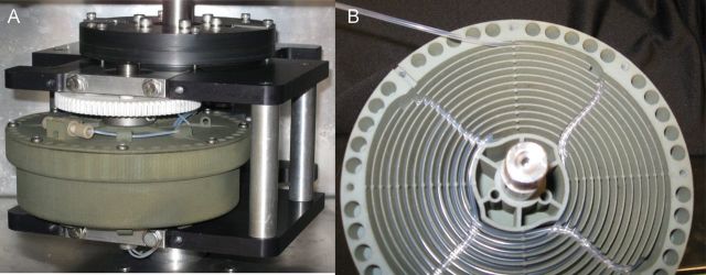
For many years, high-speed countercurrent chromatography conducted in open tubing coils has been widely used for the separation of natural and synthetic compounds. In this method, the retention of the stationary phase is solely provided by the Archimedean screw effect by rotating the coiled column in the centrifugal force field. However, the system fails to retain enough of the stationary phase for polar solvent systems such as the aqueous-aqueous polymer phase systems. To address this problem, the geometry of the coiled channel was modified to a spiral configuration so that the system could utilize the radially acting centrifugal force. This successfully improved the retention of the stationary phase. Two different types of spiral columns were fabricated: the spiral disk assembly, made by stacking multiple plastic disks with single or four interwoven spiral channels connected in series, and the spiral tube assembly, made by inserting the tetrafluoroethylene tubing into a spiral frame (spiral tube support). The capabilities of these column assemblies were successfully demonstrated by separations of peptides and proteins with polar two-phase solvent systems whose stationary phases had not been well retained in the earlier multilayer coil separation column for high-speed countercurrent chromatography.


Figures

Figure 1.
Figure 1.
Design drawings of spiral disks with cross sections that show return channels with inner (I) and outer (O) entries: spiral disk with single spiral channel (A); spiral disk with four spiral channels (B).
Figure 2.
Figure 2.
Photos of the spiral disk assembly of one disk (A); an assembled rotor of eight disks (B).
Figure 3.
Figure 3.
Retention of stationary phase in four different spiral disk designs. Column I is a single spiral in a disk (Figure 1A) with a channel 2.0 mm deep and 2.6 mm wide and a pitch of 4 mm (distance between channels); Column II is a single spiral 3.7 mm deep and 1.5 mm wide with 4 mm pitch, Column III is a disk of four interwoven spirals, as shown in Figure 1B, with the same dimensions of Column I, but with a distance of 16 mm between channels (16 mm pitch); Column IV is a four-spiral disk with the same dimensions of Column II except for a pitch of 16 mm. The sample types with their solvent systems are indicated and further details are in the text.
Figure 4.
Figure 4.
Head and tail orientation of the spiral (disk and STS rotors), which are clockwise from the center out and change with the direction of rotation (28). The top of the spiral is the inner terminal and winds clockwise to the other end at the bottom, outer or peripheral terminal. The flow of either mobile phase [upper phase (U) or lower phase (L)] can be into the top (inner) or in from the bottom (outer). Thus, the inner terminal is the head in the clockwise rotation and conversely, the outer terminal is the head in counterclockwise. For example, “L-I-T” indicates that the lower phase is pumped into the inner entry of the spiral in the tail to head direction with counterclockwise rotation. “U-O-H” means that the upper phase is pumped in from the outer entry (bottom) in counterclockwise revolution.
Figure 5.
Figure 5.
Modified channel configurations of the spiral disk. Portions of photos of the disks: bead-chain spiral disk (A); locular spiral disk (B); barricaded spiral disk (C).
Figure 6.
Figure 6.
Photo of mixer-settler spiral disk detail. The barricaded disk is made of injection molded polyethylene containing glass beads (CC Biotech).
Figure 7.
Figure 7.
Protein separations by mixer-settler CCC with an eight-plate barricaded spiral disk assembly with 160 mL capacity: separation of a protein mix of 5–6 mg each of cytochrome c, myoglobin, ovalbumin, lysozyme and bovine serum albumin (which was retained in the column) at 800 rpm and 0.25 mL/min with 280 nm detection, in which the retention of the stationary phase was 52% in the solvent system of 12.5% (w/w) PEG-1000 and 12.5% (w/w) K2HPO4 with the lower mobile phase (A); separation of a mix of five proteins, 5 mg of cytochrome c and 20 mg each of human serum albumin, β-lactoglobulin, α-chymotrypsin and trypsinogen in the solvent system consisting of PEG1000-K2HPO4–KH2PO4–H2O (16:8.3:4.2:71.5, w/w); flow rate: 0.5 mL/min; rpm: 1,000; stationary phase retention: 53.6% (B).
Figure 8.
Figure 8.
Hydrophobic peptide SAGSADQYLAVPQAPYQWA. An amount of 62 mg was loaded in sec-butanol–0.1% aqueous TFA with the lower mobile phase at 1 mL/min and 800 rpm. The chromatogram is a plot of the absorbance at 280 nm of the fractions (A). The analysis of fractions was performed by HPLC and pure fractions were pooled and dried down. The final analysis of pooled fractions was conducted by HPLC, as shown in Figure 8B. Here is shown the analysis of the crude (top line) and fractions 67–70 (bottom line). Fractions from 54 to 75 were pure (B).
Figure 9.
Figure 9.
The K of the peptide KKANELIAYLKQATK was measured in various solvent systems and the solvent system with a K close to 1 was n-butanol–1% TFA with K = 0.45. Samples of 30 mg were chromatographed in the two elution modes (A). The fractions were analyzed and the highest purity pooled and dried. The recovery levels of >99% and >90% purity are indicated. In the upper mobile phase condition, at which the compound spent more time in the system, more highly purified peptide was recovered (28) (B).
Figure 10.
Figure 10.
Design drawing of the spiral tube support (A); photo of first STS rotor fabricated in aluminium (B).
Figure 11.
Figure 11.
Photographs of the spiral tube support: plastic (nylon) spiral tube support made by laser lithography manufactured by CC Biotech (www.ccbiotech.us); also shown is the assembled STS with the planetary gear also made of nylon and cover attached with holds for the flow tubing mounted in a planetary centrifuge (A); view of the opened rotor showing spirals and radial return channels with tubing inserted (B).
Figure 12.
Figure 12.
Photo of FEP tubing, 1.6 mm o.d.: the top is cross-pressed and the bottom is flat-twisted, as described in the text (A); protein separations by cross-pressed tubing, which is also compressed in the radial grooves of the STS, at various revolution speeds and flow rates (B). PTFE tubing of 1.35 mm i.d. in 15 spiral layers with a total capacity of 85 mL; solvent system: 12.5% (w/w) PEG-1000 and 12.5% (w/w) KH2PO4 in water; sample: lysozyme and myoglobin, each 5 mg in 1 mL of upper phase; elution mode: L-I-T; detection: 280 nm.
Figure 13.
Figure 13.
STS separation of the peptide GIHIGPGRAFYAARK in the L-I-T elution mode with a sample load of 100 mg (bottom line) and 50 mg (lower middle line). HPLC analysis is below. More details are in the text.
Figure 14.
Figure 14.
Separation of adenosine and its three nucleotides. Experimental conditions: sample, adenosine, AMP, AMP, ADP and ATP, each 0.5 mg in 0.5 mL upper phase; solvent system, ethanol–50% saturated aqueous ammonium sulfate (1:2, v/v) (System 20, Table V); flow rate, 0.5 mL/min; revolution, 750 rpm; retention of stationary phase, 60%.

References

    1. Ito Y., Bowman R.L. Countercurrent chromatography: Liquid-liquid partition chromatography without solid support. Science. 1970;167:281–283. - PubMed
    1. Ito Y., Bowman R.L. Countercurrent chromatography: Liquid-liquid partition chromatography without solid support. Journal of Chromatographic Science. 1970;8:315–323. - PubMed
    1. Ito Y., Bowman R.L. Countercurrent chromatography. Analytical Chemistry. 1971;43 69A.
    1. Ito Y., Bowman R.L. Countercurrent chromatography with the flow-through coil planet centrifuge. Journal of Chromatographic Science. 1973;11:284–291. - PubMed
    1. Ito Y. New York, NY: Marcel Dekker, Inc; 1988. Principle and instrumentation of countercurrent chromatography. In Countercurrent chromatography: Theory and practice, Chapter 3; pp. 79–492.

Publication types

MeSH terms