The use of polyurethane as an elastomer in thermoplastic microfluidic devices and the study of its creep properties
- PMID: 23868507
- PMCID: PMC3895499
- DOI: 10.1002/elps.201300160
The use of polyurethane as an elastomer in thermoplastic microfluidic devices and the study of its creep properties
Abstract
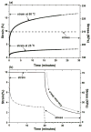
We report using polyurethane (PU) as an elastomer in microvalves integrated with thermoplastic microfluidic devices. Elastomer-based microvalves have been used in a number of applications and the elastomer often used is PDMS. Although it is a convenient material for prototyping, PDMS has been recognized to possess shortcomings such as solvent incompatibility and unfavorable manufacturability. We investigated the use of PU as an elastomer to address the challenges. A reliable method was developed to bond hybrid materials such as PU and cyclic olefin copolymer. The film thickness from 3.5 to 24.5 μm was studied to identify an appropriate thickness of PU films for desirable elasticity in microvalves. We integrated PU with thermally actuated, elastomer-based microvalves in thermoplastic devices. Valve actuations were demonstrated, and the relationship between the valve actuation time and heater power was studied. We compared PU with PDMS in terms of their microvalve performance. Valves with PDMS failed to function after two weeks since the thermal-sensitive solution evaporated through porous PDMS membrane, whereas the same valve with PU functioned properly after eight months. In addition, we evaluated the creep and creep recovery of PU, which is a common phenomenon of viscoelastic materials and is related to the long-term elastic property of PU after prolonged use.
Keywords: Bonding; Creep; Elastomer; Microvalves; Polyurethane.
© 2013 WILEY-VCH Verlag GmbH & Co. KGaA, Weinheim.
Figures


Similar articles
-
Mechanical characterisation of polyurethane elastomer for biomedical applications.J Mech Behav Biomed Mater. 2010 Jan;3(1):51-62. doi: 10.1016/j.jmbbm.2009.03.005. Epub 2009 Apr 8. J Mech Behav Biomed Mater. 2010. PMID: 19878902
-
Chemical-assisted bonding of thermoplastics/elastomer for fabricating microfluidic valves.Anal Chem. 2011 Jan 1;83(1):446-52. doi: 10.1021/ac101999w. Epub 2010 Dec 1. Anal Chem. 2011. PMID: 21121689 Free PMC article.
-
Novel thermoplastic microvalves based on an elastomeric cyclic olefin copolymer.Lab Chip. 2024 Sep 10;24(18):4422-4439. doi: 10.1039/d4lc00501e. Lab Chip. 2024. PMID: 39171671 Free PMC article.
-
Kinetics of isothermal degradation studies in adhesives by thermogravimetric data: effect of hydrophilic nanosilica fillers on the thermal properties of thermoplastic polyurethane-silica nanocomposites.Recent Pat Nanotechnol. 2008;2(3):220-6. doi: 10.2174/187221008786369679. Recent Pat Nanotechnol. 2008. PMID: 19076056 Review.
-
Advances in Waterborne Polyurethane-Based Biomaterials for Biomedical Applications.Adv Exp Med Biol. 2018;1077:251-283. doi: 10.1007/978-981-13-0947-2_14. Adv Exp Med Biol. 2018. PMID: 30357693 Review.
Cited by
-
Use of vacuum bagging for fabricating thermoplastic microfluidic devices.Lab Chip. 2015 Jan 7;15(1):62-6. doi: 10.1039/c4lc00927d. Lab Chip. 2015. PMID: 25329244 Free PMC article.
-
A valve powered by earthworm muscle with both electrical and 100% chemical control.Sci Rep. 2019 Jul 8;9(1):8042. doi: 10.1038/s41598-019-44116-3. Sci Rep. 2019. PMID: 31285453 Free PMC article.
-
CO₂ Laser-Based Rapid Prototyping of Micropumps.Micromachines (Basel). 2018 May 3;9(5):215. doi: 10.3390/mi9050215. Micromachines (Basel). 2018. PMID: 30424149 Free PMC article.
-
3D-Printed Microfluidics.Angew Chem Int Ed Engl. 2016 Mar 14;55(12):3862-81. doi: 10.1002/anie.201504382. Epub 2016 Feb 8. Angew Chem Int Ed Engl. 2016. PMID: 26854878 Free PMC article. Review.
-
Recent Advances in Polymer Science and Fabrication Processes for Enhanced Microfluidic Applications: An Overview.Micromachines (Basel). 2024 Sep 6;15(9):1137. doi: 10.3390/mi15091137. Micromachines (Basel). 2024. PMID: 39337797 Free PMC article. Review.
References
-
- Oh KW, Ahn CH. J Micromech Microeng. 2006;16:R13–R39.
-
- Unger MA, Chou HP, Thorsen T, Scherer A, Quake SR. Science. 2000;288:113–116. - PubMed
-
- Melin J, Quake SR. Annu Rev Biophys Biomol Struct. 2007;36:213–231. - PubMed
-
- Weibel DB, Kruithof M, Potenta S, Sia SK, et al. Anal chem. 2005;77:4726–4733. - PubMed
Publication types
MeSH terms
Substances
Grants and funding
LinkOut - more resources
Full Text Sources
Other Literature Sources

