. 2013 Oct 18:91:8-20.
doi: 10.1016/j.visres.2013.07.007. Epub 2013 Jul 18.

The flash grab effect

Affiliations

The flash grab effect

Patrick Cavanagh et al. Vision Res. .

Abstract

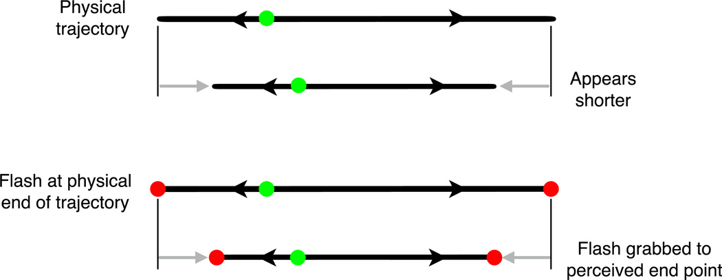
When an object moves back and forth, its trajectory appears significantly shorter than it actually is. The object appears to stop and reverse well before its actual reversal point, as if there is some averaging of location within a window of about 100 ms (Sinico et al., 2009). Surprisingly, if a bar is flashed at the physical end point of the trajectory, right on top of the object, just as it reverses direction, the flash is also shifted - grabbed by the object - and is seen at the perceived endpoint of the trajectory rather than the physical endpoint. This can shift the perceived location of the flash by as much as 2 or 3 times its physical size and by up to several degrees of visual angle. We first show that the position shift of the flash is generated by the trajectory shortening, as the same shift is seen with or without the flash. The flash itself is only grabbed if it is presented within a small spatiotemporal attraction zone around the physical end point of the trajectory. Any flash falling in that zone is pulled toward the perceived endpoint. The effect scales linearly with speed, up to a maximum, and is independent of the contrast of the moving stimulus once it is above 5%. Finally, we demonstrate that this position shift requires attention. These results reveal a new "flash grab" effect in the family of motion-induced position shifts. Although it most resembles the flash drag effect, it differs from this in the following ways: (1) it has a different temporal profile, (2) it requires attention, (3) it is about 10 times larger.

Keywords: Attention; Flash-drag effect; Motion; Position.


Figures

Figure 1
Figure 1
The flash grab. The sectored discs rotate back and forth and on each reversal of direction, a pair of vertical colored lines appear briefly. Although the lines are vertical and parallel, they may appear tilted in (red) and then out (green) at each subsequent appearance. A movie (click here) shows these effects, and the contrast of the moving texture ramps up and down to show that the lines are vertical and parallel. Fixate the central dot for best effect. Click here for all the movies related to the article.
Figure 2
Figure 2
The stimuli rotated back and forth through 90° so that the green marks or sector edges in the ring aligned alternately with horizontal then vertical. The subject rotated the stimulus so that at one end of its travel, the edges or marks appeared to align with vertical. The 4 stimuli can be seen as movies here. In the Flash + Ring stimulus, the green marks only appeared when the sector edges reached the end of travel near vertical.
Figure 3
Figure 3
Trajectory shortening versus flash grab effect. Amount of rotation required for the reversal point to appear aligned with vertical. Vertical bars are +1 SEM. In all cases the stimuli had to be rotated by around 15° in order for the reversal point to appear aligned with vertical. This was true for the isolated mark, for the mark and the ring moving together and for the sectored ring alone. Importantly, the setting was similar for the flash that appeared only at the reversal point. This flash was grabbed to the same position as the shortened endpoint of the motion trajectory.
Figure 4
Figure 4
A repeating trajectory is seen to cover a shorter extent than its physical length (Sinico et al, 2009). Our results show that if a flash is presented at the trajectory end point at the moment the motion reverses, it is seen at the same location as the perceived endpoint of the motion. This is the flash grab. The trajectories are shown as linear here for convenience; in our experiment they were circular.
Fig. 5
Fig. 5
The ring oscillated back and forth through 120°so that the sector edges aligned with vertical at each reversal. Green discs were flashed at one reversal and red at the next. Since the motions had opposite directions at the two reversals, the green and red discs appeared to be shifted away from each other in opposite directions. Seven versions of the movie were presented, each with a different physical offset between the red and green discs (they are shown aligned here and in the movie). 132 students in an Introductory Psychology class at UCSD reported whether red was to the left of green for each of the offsets to generate the data.
Figure 6
Figure 6
a) On-vs-off-the-ring stimulus. Colored discs were flashed at each motion reversal alternating between red and green and so that they were displaced in opposite directions. Observers adjusted the relative locations of the red and green flashes until they appeared to fall at the same location. The discs were presented at one of 9 different eccentricities from well outside to well inside the moving ring. b) On-vs-off-the-reversal stimulus. The green flashes were presented at different locations relative to the sector edge (here midway between, 90° phase), but always appeared at the moment of the motion reversal. Observers rotated the whole stimulus until the green flashes appeared aligned vertically. c) Synchrony stimulus. The green flashes were presented at different times relative to the moment of motion reversal, but always aligned with the sector edge. Observers rotated the whole stimulus until the green flashes appeared aligned vertically. Click here to see the movies.
Fig. 7
Fig. 7
Effect of flash distance relative to the moving ring. Large shifts are seen when the disc is in or half on the ring but these effects drop quickly with the discs off the ring. The vertical bars show ±1 SEM.
Figure 8
Figure 8
Effect of flash distance from the sector edge in the moving ring. The flash occurs at the time of the motion reversal. The largest effect is seen when the flash is located on the sector edge. The vertical bars show ±1 SEM.
Figure 9
Figure 9
Demonstration of difference of shift for a flash at the sector’s edge (vertical red bar) versus in the middle of the sector (horizontal red bar). Click here to see the movie. The red cross alternates with a green cross that will be dragged the opposite direction. If right angles have a privileged status, the flashed cross may resist the different strengths of shift for its vertical and horizontal segments and remain a right-angled cross. The demonstration shows otherwise.
Figure 10
Figure 10
Effect of timing of flash relative to moment of motion reversal. The flash always occurs at the sector edge when it is near vertical. The largest effect is seen when the flash occurs at the time of the reversal, one at the 0 ms origin and one 660 ms later. Data are combined over the two directions of reversals so the data points on the left are duplicated on the right, greyed-out and flipped in sign. Vertical bars show ±1 SEM.
Figure 11
Figure 11
a) Rotation of rings and flash locations required to perceive the green flashes as aligned to vertical plotted as a function of the contrast of the light and dark sectored ring. b) Rotation required as a function of speed of the rings (in degrees of rotation per second). Vertical bars show ±1 SEM.
Figure 12
Figure 12
Rotation of rings and flash locations required to perceive the green flashes as aligned to vertical, plotted as a function of the radial spatial frequency of the sectored ring. The filled symbols show the settings for the square wave ring and the outline symbols for the sine wave ring. Vertical bars show ±1 SEM.
Fig. 13
Fig. 13
a) Timing of the temporal order presentations, alternating blank field and rotating ring every 660 ms. Click here to see sample movies. The 0° phase flash appeared for 47 ms at the same time as the ring and then motion continued uninterrupted for 660 ms, followed by a blank field. Between 0° and 180° phase, two directions of motion were presented, one before and the opposite after the reversal with the flash appearing at the moment of the reversal. The 180° phase flash appeared at the end of 660 ms of uninterrupted motion, followed by a blank field. b) Perceived shifts as a function of temporal order. Vertical bars show ±1 SEM. The shift of the ring required for the top and bottom flashes to appear aligned to vertical is large starting immediately at 0° phase with no preceding motion and then dropping as the amount of motion trailing the flash decreases below about 200 ms (after 120° phase).
Figure 14
Figure 14
The four stimulus arrays for the endpoint alignment cask. Clear here to see sample movies. Dots oscillate up and down on the right and left. Observers adjust the relative vertical positions of the trajectories so the top end of one trajectory is horizontally aligned with the bottom end of the other. a) A single dot moves up and down on the left and another on the right. b) A set. of 15 dots on the left moves up and down asynchronously between the same top and bottom end points while a second set does the same on the right. Observers adjust the apparent endpoints of the set of trajectories to line up horizontally, top end points on the left and bottom end points on the right. c) The central dot of the 15 is colored green and observers are asked to adjust the locations of the sets of dots as before but. now so that the endpoints of just the two green trajectories line up horizontally. d) As in b) but now the sets are moved further out so the nearest dot is at the same eccentricity as the single dot in a) and the colored dot in c).
Figure 15
Figure 15
The shifts of the trajectory end points required to make them appear aligned, in percent of trajectory length for the four different conditions. Vertical bars show +1 SEM Trajectories were 10 dva in length. The absence of effect for the sets of dots attended as a group shows that the trajectory shortening is not a product of low-level motion. It appears only when the trajectory is attended as an individual motion path.

Similar articles

Cited by

References

    1. Anstis S. Kinetic edges become displaced, segregated, and invisible. In: Lam DM-K, editor. Neural mechanisms of visual perception, Proceedings of the Second Retina Research Foundation Conference. Texas: Portfolio Press; 1989.
    1. Baldo MV, Kihara AH, Namba J, Klein S. Evidence for an attentional component of the perceptual misalignment between moving and flashing stimuli. Perception. 2002;31:17–30. - PubMed
    1. Bregman AS. Auditory Scene Analysis: The Perceptual Organization of Sound. Cambridge, MA: The MIT Press; 1990.
    1. Cai RH, Schlag J. Temporal misalignment between continuous and abrupt changes. Sussex, UK: Meeting on visual location in space-time; 2002.
    1. Cai RH, Schlag J. Asynchronous feature binding and the flash-lag illusion. Investig. Ophthalm. & Vision Science. 2001;42:S711.

Publication types