

Vertical microbubble column-A photonic lab-on-chip for cultivation and online analysis of yeast cell cultures
- PMID: 23882299
- PMCID: PMC3416849
- DOI: 10.1063/1.4738587
Vertical microbubble column-A photonic lab-on-chip for cultivation and online analysis of yeast cell cultures
Abstract
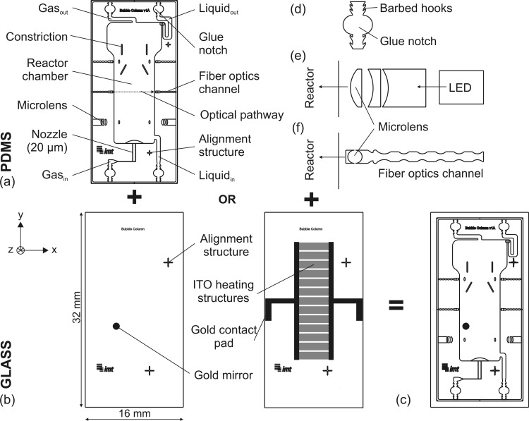
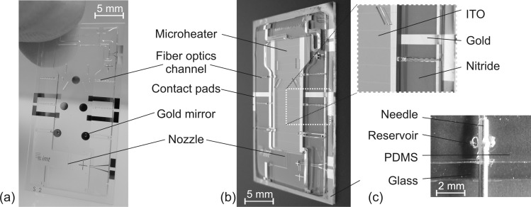
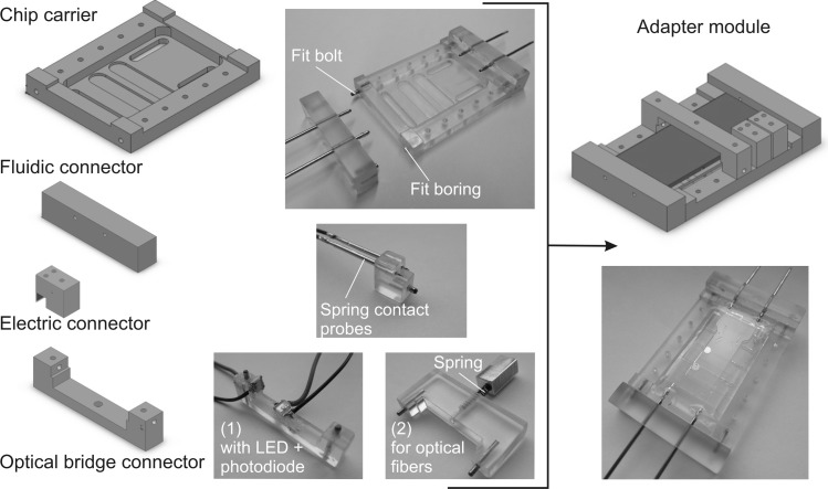
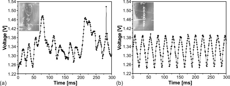
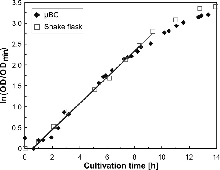
This paper presents a vertically positioned microfluidic system made of poly(dimethylsiloxane) (PDMS) and glass, which can be applied as a microbubble column (μBC) for biotechnological screening in suspension. In this μBC, microbubbles are produced in a cultivation chamber through an integrated nozzle structure. Thus, homogeneous suspension of biomass is achieved in the cultivation chamber without requiring additional mixing elements. Moreover, blockage due to produced carbon dioxide by the microorganisms-a problem predominant in common, horizontally positioned microbioreactors (MBRs)-is avoided, as the gas bubbles are released by buoyancy at the upper part of the microsystem. The patterned PDMS layer is based on an optimized two-lithographic process. Since the naturally hydrophobic PDMS causes problems for the sufficient production of microbubbles, a method based on polyelectrolyte multilayers is applied in order to allow continuous hydrophilization of the already bonded PDMS-glass-system. The μBC comprises various microelements, including stabilization of temperature, control of continuous bubble formation, and two optical configurations for measurement of optical density with two different sensitivities. In addition, the simple and robust application and handling of the μBC is achieved via a custom-made modular plug-in adapter. To validate the scalability from laboratory scale to microscale, and thus to demonstrate the successful application of the μBC as a screening instrument, a batch cultivation of Saccharomyces cerevisiae is performed in the μBC and compared to shake flask cultivation. Monitoring of the biomass growth in the μBC with the integrated online analytics resulted in a specific growth rate of 0.32 h(-1), which is almost identical to the one achieved in the shake flask cultivation (0.31 h(-1)). Therefore, the validity of the μBC as an alternative screening tool compared to other conventional laboratory scale systems in bioprocess development is proven. In addition, vertically positioned microbioreactors show high potential in comparison to conventional screening tools, since they allow for high density of integrated online analytics and therefore minimize time and cost for screening and guarantee improved control and analysis of cultivation parameters.
Figures
References
LinkOut - more resources
Full Text Sources
Other Literature Sources
Molecular Biology Databases
Miscellaneous