

Preliminary evaluation of multifield and single-field optimization for the treatment planning of spot-scanning proton therapy of head and neck cancer
- PMID: 23927306
- PMCID: PMC3732307
- DOI: 10.1118/1.4813900
Preliminary evaluation of multifield and single-field optimization for the treatment planning of spot-scanning proton therapy of head and neck cancer
Abstract
Purpose: Spot-scanning proton therapy (SSPT) using multifield optimization (MFO) can generate highly conformal dose distributions, but it is more sensitive to setup and range uncertainties than SSPT using single-field optimization (SFO). The authors compared the two optimization methods for the treatment of head and neck cancer with bilateral targets and determined the superior method on the basis of both the plan quality and the plan robustness in the face of setup and range uncertainties.
Methods: Four patients with head and neck cancer with bilateral targets who received SSPT treatment in the authors' institution were studied. The patients had each been treated with a MFO plan using three fields. A three-field SFO plan (3F-SFO) and a two-field SFO plan (2F-SFO) with the use of a range shifter in the beam line were retrospectively generated for each patient. The authors compared the plan quality and robustness to uncertainties of the SFO plans with the MFO plans. Robustness analysis of each plan was performed to generate the two dose distributions consisting of the highest and the lowest possible doses (worst-case doses) from the spatial and range perturbations at every voxel. Dosimetric indices from the nominal and worst-case plans were compared.
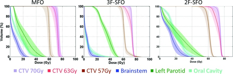
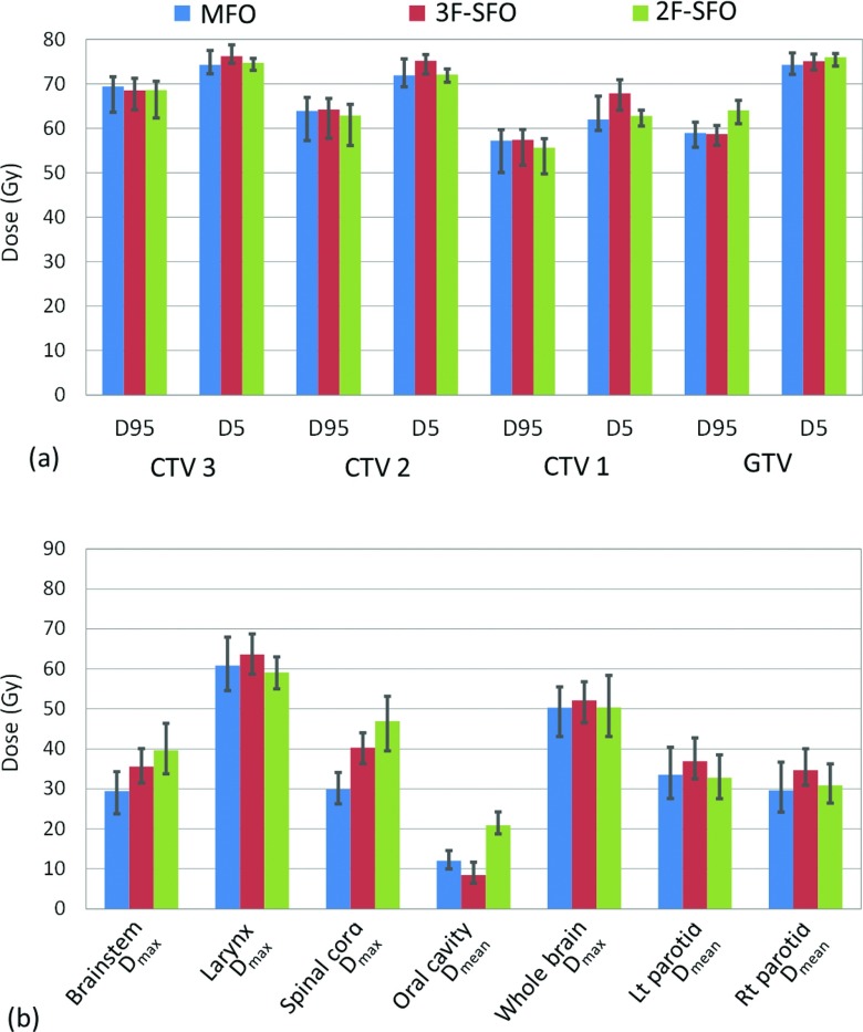
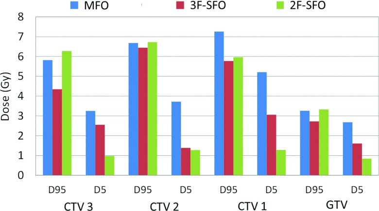
Results: The 3F-SFO plans generally yielded D95 and D5 values in the targets that were similar to those of the MFO plans. 3F-SFO resulted in a lower dose to the oral cavity than MFO in all four patients by an average of 9.9 Gy, but the dose to the two parotids was on average 6.7 Gy higher for 3F-SFO than for MFO. 3F-SFO plans reduced the variations of dosimetric indices under uncertainties in the targets by 22.8% compared to the MFO plans. Variations of dosimetric indices under uncertainties in the organs at risk (OARs) varied between organs and between patients, although they were on average 9.2% less for the 3F-SFO plans than for the MFO plans. Compared with the MFO plans, the 2F-SFO plans showed a reduced dose to the parotids for both the nominal dose and in the worst-case scenario, but the plan robustness in the target of the 2F-SFO plans was not notably greater than that of the MFO plans.
Conclusions: Compared with MFO, 3F-SFO improves plan robustness in the targets but degrades dose sparing in the parotids in both the nominal and worst-case scenarios. Although 2F-SFO improves parotid sparing compared with MFO, it produces little improvement in plan robustness. Therefore, considering its tolerable target coverage and sparing of OARs in worst-case scenarios, the authors recommend MFO as the planning method for the treatment of head and neck cancer with bilateral targets.
Figures

References
-
- Lomax A. J., Boehringer T., Coray A., Egger E., Goitein G., Grossmann M., Juelke P., Lin S., Pedroni E., Rohrer B., Roser W., Rossi B., Siegenthaler B., Stadelmann O., Stauble H., Vetter C., and Wisser L., “Intensity modulated proton therapy: A clinical example,” Med. Phys. 28, 317–324 (2001). 10.1118/1.1350587 - DOI - PubMed
-
- Zhu X. R., Poenisch F., Song X., Johnson J. L., Ciangaru G., Taylor M. B., Lii M., Martin C., Arjomandy B., Lee A. K., Choi S., Quynh Nhu N., Gillin M. T., and Sahoo N., “Patient-specific quality assurance for prostate cancer patients receiving spot scanning proton therapy using single-field uniform dose,” Int. J. Radiat. Oncol., Biol., Phys. 81, 552–559 (2011). 10.1016/j.ijrobp.2010.11.071 - DOI - PubMed
-
- Lomax A. J., “Intensity modulated proton therapy” Proton and Charged Particle Radiotherapy (Lippincott Williams & Wilkins, Boston, MA, 2008).
-
- Gillin M. T., Sahoo N., Bues M., Ciangaru G., Sawakuchi G., Poenisch F., Arjomandy B., Martin C., Titt U., Suzuki K., Smith A. R., and Zhu X. R., “Commissioning of the discrete spot scanning proton beam delivery system at The University of Texas MD Anderson Cancer Center, Proton Therapy Center, Houston,” Med. Phys. 37, 154–163 (2010). 10.1118/1.3259742 - DOI - PMC - PubMed
Publication types
MeSH terms
Substances
Grants and funding
LinkOut - more resources
Full Text Sources
Other Literature Sources
Medical
