. 2010 Oct 1;9(4-5):897-904.
doi: 10.1007/s10404-010-0609-0.

A Microfluidic Passive Pumping Coulter Counter

Affiliations

A Microfluidic Passive Pumping Coulter Counter

Amy L McPherson et al. Microfluid Nanofluidics. .

Abstract

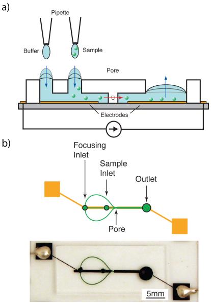
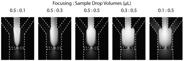
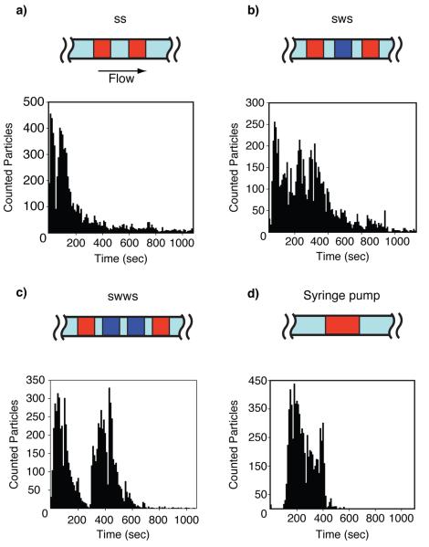
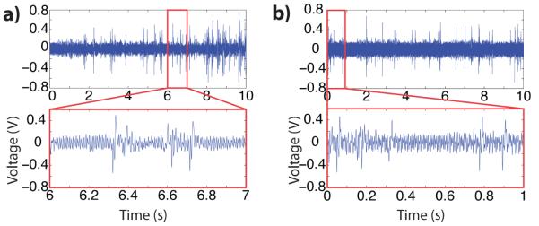
A microfluidic device using on-chip passive pumping was characterized for use as a particle counter. Flow occurred due to a Young-Laplace pressure gradient between two 1.2 mm diameter inlets and a 4 mm diameter reservoir when 0.5μ L fluid droplets were applied to the inlets using a micropipette. Polystyrene particles (10μm diameter) were enumerated using the resistive pulse technique. Particle counts using passive pumping were within 13% of counts from a device using syringe pumping. All pumping methods produced particle counts that were within 16% of those obtained with a hemocytometer. The effect of intermediate wash steps on particle counts within the passive pumping device was determined. Zero, one, or two wash droplets were loaded after the first of two sample droplets. No statistical difference was detected in the mean particle counts among the loading patterns (p > 0.05). Hydrodynamic focusing using passive pumping was also demonstrated.

Keywords: Colloid; Enumeration; Microfluidics; Resistive Pulse.


Figures

Fig. 1
Fig. 1
(a) A micropipette applies a small volume of fluid to the focusing and sample inlets. These inlets possess a higher internal pressure than the large reservoir drop. Due to this pressure gradient, fluid moves downstream towards the reservoir until the pressures equilibrate. Particles suspended in the sample fluid traverse the pore as they move downstream. The electrical resistance of the device is briefly changed while a particle is in the pore, yielding a detectable voltage pulse. (b) Focusing channels are used to align the particles before they traverse the pore, resulting in a more consistent signal. To minimize leaking, electrodes were fabricated lengthwise down the channel, stopping a short distance (100μm) on either side of the pore.
Fig. 2
Fig. 2
FITC images of hydrodynamic focusing (HDF) for ratios of focusing droplet volume to sample droplet volume. Drops of deionized water were applied to the focusing inlet, and a solution of fluorescein in deionized water was loaded into the sample inlet. The focusing drop fed the outer two side channels simultaneously, while the sample drop fed the central channel. Due to channel design, the fluidic resistance is approximately equal between the focusing inlet and the pore and between the sample inlet and the pore. When the focusing drop has a larger radius than the sample drop, the focusing streams are wider due to a higher pressure. When the ratio is reversed, the sample stream is wider than the focusing streams.
Fig. 3
Fig. 3
Pulse counts versus time for passive pumping devices using the droplet patterns (a) SS, (b) SWS, (c) SWWS. (d) A syringe pump was used for the control. Distinct peaks that exponentially decay can be seen in the passive pumping histograms, representing the bolus of particles from each sample droplet. The continuous flow of the syringe pump resulted in a well-defined bolus of particles. S = sample droplet. W = wash (saline) droplet.
Fig. 4
Fig. 4
Ten-second voltage recordings for (a) passive pumping with zero wash droplets between samples and (b) syringe pump generating a 1μL/min flow rate. Insets: detail of one-second interval.

Similar articles

Cited by

References

    1. Arndt S, Seebach J, Psathaki K, Galla H, Wegener J. Bioelectrical impedance assay to monitor changes in cell shape during apoptosis. Biosens Bioelectron. 2004;19(6):583–594. - PubMed
    1. Ateya D, Sachs F, Gottlieb P, Besch S, Hua S. Volume cytometry: Microfluidic sensor for high-throughput screening in real time. Analytical Chemistry. 2005;77(5):1290–1294. - PubMed
    1. Benazzi G, Holmes D, Sun T, Mowlem MC, Morgan H. Discrimination and analysis of phytoplankton using a microfluidic cytometer. IET Nanobiotechnol. 2007;1(6):94–101. - PubMed
    1. Berthier E, Beebe DJ. Flow rate analysis of a surface tension driven passive micropump. Lab Chip. 2007;7(11):1475–1478. - PubMed
    1. Berthier E, Warrick J, Yu H, Beebe D. Managing evaporation for more robust microscale assays part 2. characterization of convection and diffusion for cell biology. Lab Chip. 2008;8(6):860. - PMC - PubMed

LinkOut - more resources