. 2013 Aug 7;8(8):e71478.
doi: 10.1371/journal.pone.0071478. Print 2013.

Multiparametric, longitudinal optical coherence tomography imaging reveals acute injury and chronic recovery in experimental ischemic stroke

Affiliations

Multiparametric, longitudinal optical coherence tomography imaging reveals acute injury and chronic recovery in experimental ischemic stroke

Vivek J Srinivasan et al. PLoS One. .

Abstract

Progress in experimental stroke and translational medicine could be accelerated by high-resolution in vivo imaging of disease progression in the mouse cortex. Here, we introduce optical microscopic methods that monitor brain injury progression using intrinsic optical scattering properties of cortical tissue. A multi-parametric Optical Coherence Tomography (OCT) platform for longitudinal imaging of ischemic stroke in mice, through thinned-skull, reinforced cranial window surgical preparations, is described. In the acute stages, the spatiotemporal interplay between hemodynamics and cell viability, a key determinant of pathogenesis, was imaged. In acute stroke, microscopic biomarkers for eventual infarction, including capillary non-perfusion, cerebral blood flow deficiency, altered cellular scattering, and impaired autoregulation of cerebral blood flow, were quantified and correlated with histology. Additionally, longitudinal microscopy revealed remodeling and flow recovery after one week of chronic stroke. Intrinsic scattering properties serve as reporters of acute cellular and vascular injury and recovery in experimental stroke. Multi-parametric OCT represents a robust in vivo imaging platform to comprehensively investigate these properties.


Conflict of interest statement

Competing Interests: The authors have declared that no competing interests exist.

Figures

Figure 1
Figure 1. Schematic of spectral/Fourier domain OCT system and microscope.
A dual-superluminescent diode (SLD) light source achieved an axial resolution of 3.5 µm in tissue. The OCT scanning system was built on a modified Nikon FN1 microscope platform, with a CCD camera and dichroic mirror for simultaneous viewing of the brain under visible light (570 nm ±5 nm).
Figure 2
Figure 2. OCT angiography enables depth-resolved imaging of capillary perfusion.
(A) Raw OCT image (logarithmic scale), acquired with the 10× objective, with the skull and coverslip labeled. (B) Normalized OCT angiogram (linear scale). (C) Segmentation of the image into three regions comprising the skull and dura, surface vessels (<100 µm depth), and deep vessels (>100 µm depth). (D) Surface vasculature map shows pial vasculature as well as diving arterioles and ascending venules. (E) Deep vasculature map shows perfusion in capillary beds. “Tails” from superficial vessels also appear in the map of deep vasculature, due to multiple scattering and motion correction errors. (F) Combination of surface and deep vasculature maps (surface - red channel, deep - green channel).
Figure 3
Figure 3. En face integration method quantifies flow without requiring explicit knowledge of vessel angle.
An ascending vein with flow towards the incident probe beam is bisected by the en face plane. A red blood cell is shown, with a velocity vector given by v, while the magnitude of the velocity axial (z) projection is given by |vz|. Flow is obtained by integrating the axial projection of velocity over the en face plane.
Figure 4
Figure 4. High resolution cortical flow mapping is achieved by calculating flow values in individual ascending venules and diving arterioles.
(A) OCT angiography, after one week permanent dMCAO, in the MCA-ACA boundary region is shown, with prominent collateral growth (white arrows). Two-dimensional maps showing the axial projection of velocity in vessels either supplying (B) or draining (C) the cortex were created. (D) A flow histogram showed that venular locations (flow draining the cortex) were more numerous than arteriolar locations (flow supplying the cortex), but that the magnitude of flow per venular location was smaller. Thus, absolute cortical blood flow calculated from summing over all venules was 110 mL/100 g/min, while the cortical flow calculated from summing over all arterioles was 126 mL/100 g/min. (E) A spatial map of flow was formed by averaging arteriolar and (inverted) venular flow maps, and blurring with a 2-D Gaussian function with a half-width at half maximum of 0.2 mm.
Figure 5
Figure 5. Analysis of acute cellular scattering changes after transient fMCAO.
(A) Cross-sectional image (60 minutes after reperfusion) showing reduced OCT signal penetration on the lateral side compared to the medial side. Two exemplary axial lines (red and green) are chosen for analysis of the OCT signal. (B) Plots of logarithmic OCT signal vs. depth along these lines, after averaging (80 µm transverse, 35 µm axial), along with second-order polynomial fits at the two points labeled 1 (non-infarct) and 2 (infarct). (C) Plot of the second-order coefficient from the polynomial fit (p2), showing a transition in the curvature from concave down (lateral side) to concave up (medial side). (D–F) Images of zeroth, first, and second order polynomial coefficients from the polynomial fit. In the second-order coefficient image (F), a clear transition in scattering characteristics is seen.
Figure 6
Figure 6. Capillary non-perfusion during fMCAO predicts cellular scattering changes leading to eventual infarction.
(A–C) OCT angiograms at baseline, during fMCAO, and 60 minutes after filament withdrawal. During fMCAO (B), a capillary non-perfused region is apparent, as demarcated with a solid white line. (D–F) OCT cross-sectional images on a logarithmic scale, with minor differences in alignment, show changing signal characteristics in the lateral portion of the cranial window after reperfusion (F). (G–I) Images of the curvature of the OCT signal vs. depth at baseline, during fMCAO, and 60 minutes after reperfusion show this evolution. In (H–I), the capillary non-perfusion boundary from (B) is shown as a dotted white line. In particular, the tissue with anomalous scattering properties (i.e., the log OCT signal vs. depth is concave down) after reperfusion corresponds well to the non-perfused tissue during fMCAO. No comparable changes were observed in the contralateral hemisphere.
Figure 7
Figure 7. Correlation of acute cellular scattering changes after transient fMCAO with MAP2 immunohistochemistry, approximately two hours after reperfusion.
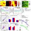
(A) Coronal section shows a clear delineation of the lesion, with absent MAP2 immunoreactivity. Sagittal OCT cross-sections in the infarct (B) and peri-infarct (C) regions show differences in signal characteristics. (D) When the logarithmic signal change over the first 250 microns of cortical tissue is displayed en face, a clear border is observed, delineating the infarct. The OCT signal characteristics of the contralateral cortex (E–G) are comparable to those of the peri-infarct cortex. (H) Curvature differences, determined from Equation 3, are also observed between infarct and peri-infarct cortical regions, as suggested by Figure 5. (I–J) Aberrant cortical cellular morphology, visualized approximately 2 hours after reperfusion by Cresyl Violet near the ipsilateral lesion boundary (black arrow), may partially account for the observed scattering changes.
Figure 8
Figure 8. Spatially heterogeneous flow and diameter changes were observed during fMCAO and after reperfusion.
Absolute flow maps show uniform flow at baseline (A), preferentially reduced MCA flow during occlusion (B), and restored MCA flow, with a persistent ACA flow deficit, after reperfusion (C). (D) An angiogram from the same animal during occlusion shows capillary non-perfusion in the lateral portion of the cranial window, presumably delineating the region destined for infarction, as suggested by Figure 6. (E–F) Regional blood flow was estimated as a function of distance between the MCA and ACA supplied territories. Flow was restored to baseline values on the MCA side after reperfusion, while a flow deficit persisted on the ACA side (E). These changes were not mirrored by the contralateral hemisphere (F). (G–H) Consistent with these results, vessels preferentially dilated in the MCA region, and constricted in the ACA region after reperfusion. (I) Remarkably, even along a single artery, both dilation and constriction were observed, depending on the earlier presence of nearby capillary non-perfusion.
Figure 9
Figure 9. Remodeling in chronic stroke was investigated with a permanent dMCAO model.
Blood flow was measured in both diving arterioles and ascending venules. (A) Regional blood flow was estimated as a function of distance between the MCA and ACA supplied territories. While flow was relatively uniform before occlusion, a gradient in flow was observed after one week permanent dMCAO. (B) Flow was reduced on the MCA side, while flow was preserved near the ACA side, showing the impact of the collateral ACA supply. (C–D) Diameter changes were evident in both MCA and ACA arteries as well as collaterals. (E) Doppler OCT revealed a reversal in flow direction in major MCA branches. This flow reversal is due to the large pressure drop in the occluded branches, and may be further enhanced by collateral growth and artery dilation.
Figure 10
Figure 10. OCT angiography suggested remodeling in the border zone during distal MCAO.
Angiograms were acquired over a 1.5 mm x 1.5 mm field-of-view with a transverse resolution of 3.6 µm before (A) and after (B) one week permanent dMCAO. (C–D) Zoomed images show pial collateral growth (solid white arrows), dural vessel dilation (dotted white arrow), and a more irregular capillary bed (green), suggesting angiogenesis.

References

    1. Schlaug G, Benfield A, Baird AE, Siewert B, Lovblad KO, et al. (1999) The ischemic penumbra - Operationally defined by diffusion and perfusion MRI. Neurology 53: 1528–1537. - PubMed
    1. Zhang ZG, Chopp M (2009) Neurorestorative therapies for stroke: underlying mechanisms and translation to the clinic. Lancet Neurol 8: 491–500. - PMC - PubMed
    1. Ding G, Jiang Q, Li L, Zhang L, Zhang ZG, et al. (2008) Magnetic resonance imaging investigation of axonal remodeling and angiogenesis after embolic stroke in sildenafil-treated rats. J Cereb Blood Flow Metab 28: 1440–1448. - PMC - PubMed
    1. Wilt BA, Burns LD, Ho ETW, Ghosh KK, Mukamel EA, et al. (2009) Advances in Light Microscopy for Neuroscience. Ann Rev Neurosci 32: 435–506. - PMC - PubMed
    1. Dunn AK, Bolay H, Moskowitz MA, Boas DA (2001) Dynamic imaging of cerebral blood flow using laser speckle. J Cereb Blood Flow Metab 21: 195–201. - PubMed

Publication types