

MRI-based multiscale model for electromagnetic analysis in the human head with implanted DBS
- PMID: 23956789
- PMCID: PMC3727211
- DOI: 10.1155/2013/694171
MRI-based multiscale model for electromagnetic analysis in the human head with implanted DBS
Abstract
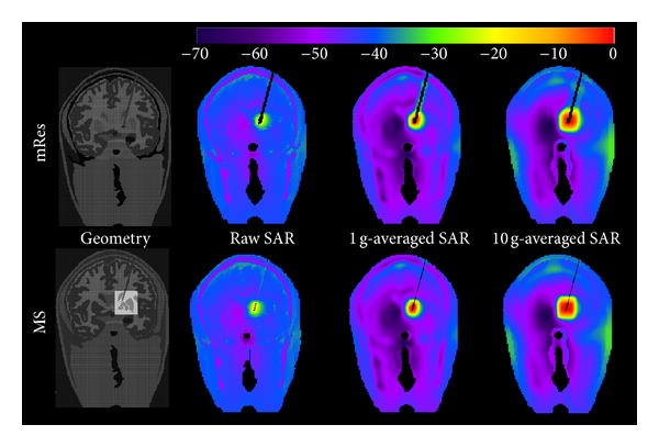
Deep brain stimulation (DBS) is an established procedure for the treatment of movement and affective disorders. Patients with DBS may benefit from magnetic resonance imaging (MRI) to evaluate injuries or comorbidities. However, the MRI radio-frequency (RF) energy may cause excessive tissue heating particularly near the electrode. This paper studies how the accuracy of numerical modeling of the RF field inside a DBS patient varies with spatial resolution and corresponding anatomical detail of the volume surrounding the electrodes. A multiscale model (MS) was created by an atlas-based segmentation using a 1 mm(3) head model (mRes) refined in the basal ganglia by a 200 μ m(2) ex-vivo dataset. Four DBS electrodes targeting the left globus pallidus internus were modeled. Electromagnetic simulations at 128 MHz showed that the peak of the electric field of the MS doubled (18.7 kV/m versus 9.33 kV/m) and shifted 6.4 mm compared to the mRes model. Additionally, the MS had a sixfold increase over the mRes model in peak-specific absorption rate (SAR of 43.9 kW/kg versus 7 kW/kg). The results suggest that submillimetric resolution and improved anatomical detail in the model may increase the accuracy of computed electric field and local SAR around the tip of the implant.
Figures


Similar articles
-
Local SAR near deep brain stimulation (DBS) electrodes at 64 and 127 MHz: A simulation study of the effect of extracranial loops.Magn Reson Med. 2017 Oct;78(4):1558-1565. doi: 10.1002/mrm.26535. Epub 2016 Oct 31. Magn Reson Med. 2017. PMID: 27797157 Free PMC article.
-
Realistic modeling of deep brain stimulation implants for electromagnetic MRI safety studies.Phys Med Biol. 2018 May 4;63(9):095015. doi: 10.1088/1361-6560/aabd50. Phys Med Biol. 2018. PMID: 29637905 Free PMC article.
-
RF-induced heating in tissue near bilateral DBS implants during MRI at 1.5 T and 3T: The role of surgical lead management.Neuroimage. 2019 Jan 1;184:566-576. doi: 10.1016/j.neuroimage.2018.09.034. Epub 2018 Sep 19. Neuroimage. 2019. PMID: 30243973 Free PMC article.
-
Magnetic resonance imaging safety of deep brain stimulator devices.Handb Clin Neurol. 2013;116:73-6. doi: 10.1016/B978-0-444-53497-2.00007-3. Handb Clin Neurol. 2013. PMID: 24112886 Review.
-
Interventional MRI-Guided Deep Brain Stimulation Lead Implantation.Neurosurg Clin N Am. 2017 Oct;28(4):535-544. doi: 10.1016/j.nec.2017.05.007. Epub 2017 Jul 4. Neurosurg Clin N Am. 2017. PMID: 28917282 Review.
Cited by
-
A Virtual Patient Simulator Based on Human Connectome and 7 T MRI for Deep Brain Stimulation.Int J Adv Life Sci. 2014;6(3-4):364-372. Int J Adv Life Sci. 2014. PMID: 25705324 Free PMC article.
-
Numerical Simulations of Realistic Lead Trajectories and an Experimental Verification Support the Efficacy of Parallel Radiofrequency Transmission to Reduce Heating of Deep Brain Stimulation Implants during MRI.Sci Rep. 2019 Feb 14;9(1):2124. doi: 10.1038/s41598-018-38099-w. Sci Rep. 2019. PMID: 30765724 Free PMC article.
-
A Study on the Feasibility of the Deep Brain Stimulation (DBS) Electrode Localization Based on Scalp Electric Potential Recordings.Front Physiol. 2019 Jan 4;9:1788. doi: 10.3389/fphys.2018.01788. eCollection 2018. Front Physiol. 2019. PMID: 30662407 Free PMC article.
-
Local SAR near deep brain stimulation (DBS) electrodes at 64 and 127 MHz: A simulation study of the effect of extracranial loops.Magn Reson Med. 2017 Oct;78(4):1558-1565. doi: 10.1002/mrm.26535. Epub 2016 Oct 31. Magn Reson Med. 2017. PMID: 27797157 Free PMC article.
-
Realistic modeling of deep brain stimulation implants for electromagnetic MRI safety studies.Phys Med Biol. 2018 May 4;63(9):095015. doi: 10.1088/1361-6560/aabd50. Phys Med Biol. 2018. PMID: 29637905 Free PMC article.
References
-
- Shellock FG, Spinazzi A. MRI safety update 2008: part 2, screening patients for MRI. American Journal of Roentgenology. 2008;191(4):1140–1149. - PubMed
-
- Baker KB, Tkach JA, Phillips MD, Rezai AR. Variability in RF-induced heating of a deep brain stimulation implant across MR systems. Journal of Magnetic Resonance Imaging. 2006;24(6):1236–1242. - PubMed
-
- Stevenson B, Dabney W, Frysz C. Issues and design solutions associated with performing MRI scans on patients with active implantable medical devices. Proceedings of the Annual International Conference of the IEEE Engineering in Medicine and Biology Society. 2007;2007:6167–6170. - PubMed
-
- Buchli R, Boesiger P, Meier D. Heating effects of metallic implants by MRI examinations. Magnetic Resonance in Medicine. 1988;7(3):255–261. - PubMed
-
- Chou C-K, McDougall JA, Chan KW. RF heating of implanted spinal fusion stimulator during magnetic resonance imaging. IEEE Transactions on Biomedical Engineering. 1997;44(5):367–373. - PubMed
Publication types
MeSH terms
Grants and funding
LinkOut - more resources
Full Text Sources
Other Literature Sources
Medical
Research Materials
Miscellaneous
