

doi: 10.2174/157340510791268533.
X-ray phase sensitive imaging methods: basic physical principles and potential medical applications
Affiliations
- PMID: 23970846
- PMCID: PMC3747977
- DOI: 10.2174/157340510791268533
Item in Clipboard
X-ray phase sensitive imaging methods: basic physical principles and potential medical applications
Curr Med Imaging Rev.
.
Abstract
Phase sensitive imaging theoretically allows for a drastic reduction in x-ray dose while simultaneously achieving comparable or better spatial and contrast resolution compared to traditional x-ray absorption based imaging. Several techniques exist to extract the phase information from an x-ray signal, including x-ray interferometry, diffraction enhanced imaging, in-line holography, coded aperture x-ray imaging, and grating-based interferometry. The physics of each method is reviewed, along with the potential clinical applications.
Keywords: CT; DEI; in-line holography; phase contrast; x-ray interferometry.
Figures
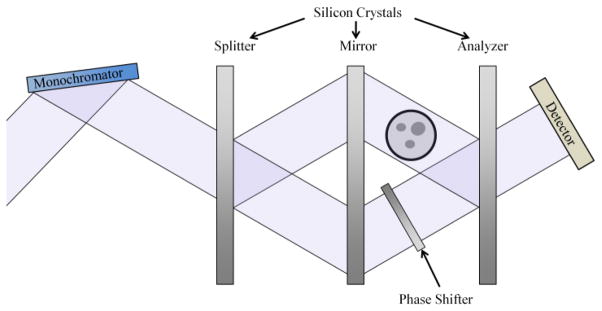
An x-ray interferometer setup. Three crystal plates, the splitter, mirror, and analyzer, operate as the components of an x-ray interferometer. The system generates interference fringes produced by phase changes in one of the beams as it passes through the object.
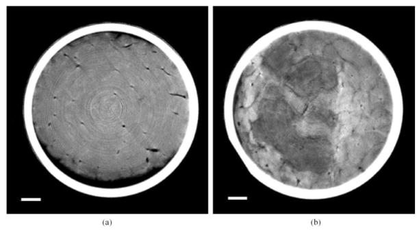
(a) Phase-contrast X-ray CT image of normal rat liver. (b) Phase-contrast X-ray CT image of VX-2 cancer lesion of rabbit’s liver. Scale bar: 1 mm [13].
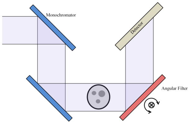
A diffraction-enhanced imaging setup. An x-ray beam passes through a monochromator, then the object, and finally is analyzed by the angular filter before being incident on the detector. Variation in the refraction through the object causes changes in the relative angle on the analyzer, changing the reflection and contrast produced.
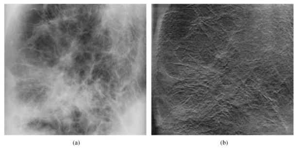
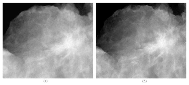
Full-thickness breast specimen image acquired using a GE Senographe 2000D (GE, Paris, France) (a) conventional digital mammographic system and (b) a corresponding image acquired using the compact diffraction-enhanced imaging system [30].
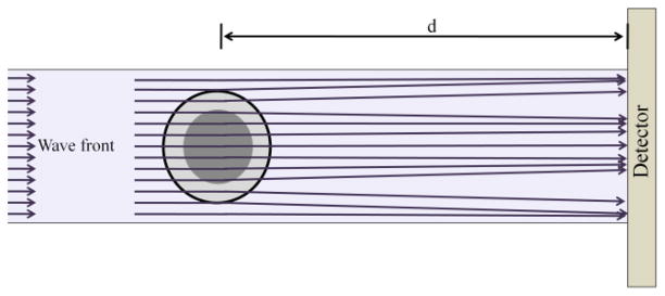
An in-line holography illustration. A wave-front passes through an object which distorts the wave-front. The detector is placed behind the object, at a sufficient distance d, to allow interference fringes to form without additional x-ray imaging optics.
(a) Attenuation and (b) phase contrast image of lumpectomy specimen. Both images were acquired at 40kVp with the same entrance exposure. The images were acquired using prototype systems developed at the University of Oklahoma (Dr. Hong Liu), in collaborations with University of Alabama at Birmingham (Dr. Xizeng Wu) and University of Iowa (Dr. Laurie Fajardo). [Courtesy: Dr. Hong Liu, University of Oklahoma]
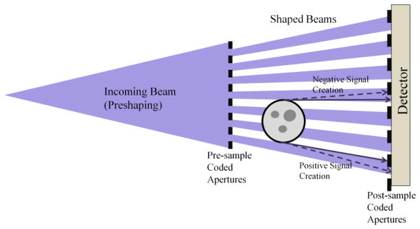
Coded Aperture imaging system illustration. An incoming beam, from an x-ray tube in this illustration, is incident on a coded aperture, which attenuates a portion of the beam, creating many narrow shaped beams. A portion of the beams proceed through the object, which refracts them on their path to the detector. The addition of a second coded aperture before the detector allows the deflections of the beams to be recorded as intensity changes.
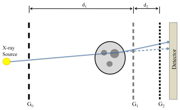
Illustration of the Talbot-Lau grating based interferometer system. An incoherent x-ray source provided by a standard x-ray tube is placed behind the source grating, G0, which cuts the beam into a series of vertical beamlets, increasing the spatial coherence of the beam. The beam passes through the image object and then the phase grating, G1, which introduces a relative π-phase shift into beam at a 50% duty cycle. This causes a replication of the grating pattern at fractional Talbot distances. The final analyzer grating, G2, is placed at a fractional Talbot distance.
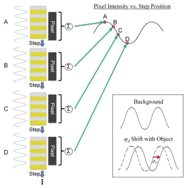
Illustration of the phase-stepping method for extraction of the differential phase contrast signal from the measured projection data. Each letter represents one step position of the analyzer grating. The electric field intensity at the face of the grating is a replication of the phase grating pattern and is in the same position for each of the phase steps of a given view. The total contribution of the field which is transmitted through the grating is summed by each pixel. The intensity at each pixel is recorded at each step position and the phase of the pixel intensity modulation is compared between when the object is present compared to when it is not.
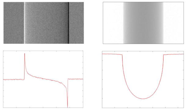
Differential phase and absorption projection images of a plastic rod. The left column contains a differential phase contrast projection (top left), a line profile through the rod (bottom left). The differential line profile shows the nature of the differential projection image, where only regions of sudden change will contain contrast, e.g. the edges of a rod. The right column shows a typical attenuation image (top right) and line profile (bottom right), where the largest signal comes from the most attenuating part of the image, the center.
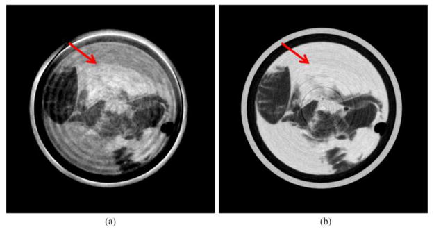
Reconstructed (a) phase contrast and (b) conventional attenuation images of a breast tissue sample containing a highly malignant carcinoma. The phase contrast image shows significant contrast between the central tissue portion and water near the outer wall of the cylinder (indicated by arrow). The absorption image shows little to no contrast in this region, even in a narrow viewing
References
-
- Wu X, Dean A, Liu H. X-ray diagnostic techniques. Chapter 26. CRC Press; Tampa, Florida: 2003. Biomedical photonics handbook; pp. 26–21.pp. 26–34.
-
- Fitzgerald R. Phase-sensitive x-ray imaging. Physics Today. 2000;53:23–26.
-
- Alvarez RE, Macovski A. Energy-selective reconstructions in x-ray computerised tomography. Physics in medicine and biology. 1976;21:733–744. - PubMed
-
- Born M, Wolf E. Principles of Optics. Pergamon Press; New York: 1993.
-
- Als-Nielsen J, McMorrow D. Elements of Modern X-ray Physics. John Wiley & Sons Ltd; New York: 2004.
Grants and funding
LinkOut - more resources
Full Text Sources
Other Literature Sources