Review
. 2014 Jan;10(1):11-25.
doi: 10.1016/j.actbio.2013.08.022. Epub 2013 Aug 22.

Electrospun scaffolds for tissue engineering of vascular grafts

Affiliations
Review

Electrospun scaffolds for tissue engineering of vascular grafts

Anwarul Hasan et al. Acta Biomater. 2014 Jan.

Abstract

There is a growing demand for off-the-shelf tissue engineered vascular grafts (TEVGs) for the replacement or bypass of damaged arteries in various cardiovascular diseases. Scaffolds from the decellularized tissue skeletons to biopolymers and biodegradable synthetic polymers have been used for fabricating TEVGs. However, several issues have not yet been resolved, which include the inability to mimic the mechanical properties of native tissues, and the ability for long-term patency and growth required for in vivo function. Electrospinning is a popular technique for the production of scaffolds that has the potential to address these issues. However, its application to human TEVGs has not yet been achieved. This review provides an overview of tubular scaffolds that have been prepared by electrospinning with potential for TEVG applications.

Keywords: Electrospinning; Mechanical properties; Tissue engineering; Tubular scaffolds; Vascular grafts.


Figures

Fig. 1
Fig. 1
Tissue engineered blood vessels; A–C: the first clinically used sheet-based tissue engineered blood vessel tested on three human patients for application as high pressure arteries, (A) tissue engineered graft was implanted between the axillary vein and the humeral artery as an arteriovenous shunt, (B) the vessel exhibited normal suturing and surgical handling properties, (C) the shunt maintained high flow without signs of aneurysm or restenosis even after 6 months. Reprinted from [14] with permission from Nature Publishing Group. D–O: A comparative histological analysis of human pericyte cell-seeded TEVGs (D–I), unseeded scaffolds (J–L), and native rat aorta (M–O). The Hematoxylin and Eosin (D, G, J and M), (H&E), Masson’s trichrome (E, H, K and N), and Verhoeff-Van Gieson (F, I, L and O) stainings demonstrated remodeling of the tissue in the TEHV construct enriched with collagen and elastin similar to the native aorta. G, H and I are magnified images for the wall cross-section of D, E and F. Arrows indicate the remodeled tissue while ES stands for electrospun scaffold layer. The remaining PEUU material was unspecifically stained in black by Verhoeff-van Gieson stain in I and L. Figures reprinted from [17] with permission from Elsevier Science.
Fig. 2
Fig. 2
Schematic cross-sectional view of an artery. The arterial wall comprises of three main layers (i) adventitia, (ii) media, and (iii) intima. A layer of endothelial cell covers the internal surface of the lumen while smooth muscle cells and fibroblast cells exist in outer layers.
Fig. 3
Fig. 3
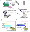
Schematics of various experimental set ups for electrospinning process for fabrication of tubular scaffolds, (A) a multilayer scaffold combining electrospinning and hydrogel fabrication. Adapted from [1] with permission from Elsevier. (B) Co-electrospinning of two polymer solutions concurrently, and (C) electrospinning with simultaneous electrospraying. Adapted from [43] with permission from American Chemical Society.
Fig. 4
Fig. 4
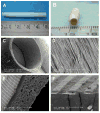
A PCL/collagen bilayer electrospun scaffold. (A) Macrostructure of the scaffold; (B) fluorescent images of the scaffold; (C–E) SEM images of different layers of the scaffold, (C) outer layer, (D) bilayer structure, and (E) interface between the inner and outer layers; (F–G) fluorescent images of EC and SMC seeded scaffold (F) EC seeded inner layer (green: CD31 expression), indicating the formation of an EC monolayer and (G) SMC seeded outer layer (red: α-SMA expression), demonstrating SMC infiltration into the outer layer (scale bar in F and G: 500 μm). Reproduced from [57] with permission from Elsevier.
Fig. 5
Fig. 5
An electrospun tubular scaffold fabricated using recombinant human tropoelastin (rTE), (A) Front view showing the length of the scaffold (7 cm in length, 4 mm inner diameter), (B) The random orientation of the rTE fibers, average diameters: 580 ± 94 nm (scale bar: 5 μm); (C) vWF (red) staining and DAPI (blue) nucleus staining, (D) vWF and DAPI staining of the control sample, (E) The EC monolayer fromed on rTE scaffold (15 wt.%) imaged after 48 hours of culturing. The cytoskeletal actin fiber was stained with rhodamine phalloidin (red) and the nuclei were stained using DAPI. Reprinted from [10] with permission from Elsevier.
Fig. 6
Fig. 6
Electrospun PU graft with micropatterns on the luminal surface, (A) length of the graft: 48 mm, (B) diameter of the graft: 4 mm. (C, D) SEM images showing the circumferential alignment of the microfibers (arrow). (D) Enlarged view of the microfibers on the graft exterior. (E, F) SEM images of the hybrid graft showing microgrooves on the luminal surface and mesh of microfibers on the exterior. The dimension in “F” are ridge width = 3.6 ± 0.2, channel width = 3.9 ± 0.1 and channel depth = 0.9 ± 0.03 μm. Adapted from [53] with permission from Elsevier.
Fig. 7
Fig. 7
Endothelial cell morphology on the micropatterned scaffold: (A–C) adhesion and spreading of cells inside microfiber patterned electrospun graft. Fluorescently stained cell nuclei (blue) and actin filaments (red) of BAECs or EA.hy926 cells (inset) at (A) 2 hours, (B) 3rd day, and (C) 5th day after seeding. (D, E) adhesion and spreading of cells inside microgrooves patterned hybrid grafts. (D) Fluorescence image of BAECs or EA.hy926 EC (inset) on 3rd day after seeding. (E) The confluent monolayer of BAEC and overlaid fluorescence image of a EA.hy926 EC monolayer (inset). (F, G) VE-cadherin staining (green) of (F) BAEC and (G) EA.hy926 monolayers on microgrooves on 7th day after seeding. The direction of microfibers and microgrooves is shown using the double-headed arrow. Reprinted from [53] with permission from Elsevier.

References

    1. Browning MB, Dempsey D, Guiza V, Becerra S, Rivera J, Russell B, et al. Multilayer vascular grafts based on collagen-mimetic proteins. Acta Biomaterialia. 2011;8:1010–21. - PubMed
    1. Tu JV, Pashos CL, Naylor CD, Chen EL, Normand SL, Newhouse JP, et al. Use of cardiac procedures and outcomes in elderly patients with myocardial infarction in the United States and Canada. New England Journal of Medicine. 1997;336:1500–5. - PubMed
    1. Ratcliffe A. Tissue engineering of vascular grafts. Matrix Biology. 2000;19:353–7. - PubMed
    1. Stegemann JP, Kaszuba SN, Rowe SL. Review: Advances in vascular tissue engineering using protein-based Biomaterials. Tissue Engineering. 2007;13:2601–13. - PMC - PubMed
    1. Dolgin E. Taking tissue engineering to heart. Nature Medicine. 2011;17:1032–5. - PubMed

Publication types