. 2013 Oct 30;32(21):2804-18.
doi: 10.1038/emboj.2013.198. Epub 2013 Sep 3.

RNA structure analysis of human spliceosomes reveals a compact 3D arrangement of snRNAs at the catalytic core

Affiliations

RNA structure analysis of human spliceosomes reveals a compact 3D arrangement of snRNAs at the catalytic core

Maria Anokhina et al. EMBO J. .

Abstract

Although U snRNAs play essential roles in splicing, little is known about the 3D arrangement of U2, U6, and U5 snRNAs and the pre-mRNA in active spliceosomes. To elucidate their relative spatial organization and dynamic rearrangement, we examined the RNA structure of affinity-purified, human spliceosomes before and after catalytic step 1 by chemical RNA structure probing. We found a stable 3-way junction of the U2/U6 snRNA duplex in active spliceosomes that persists minimally through step 1. Moreover, the formation of alternating, mutually exclusive, U2 snRNA conformations, as observed in yeast, was not detected in different assembly stages of human spliceosomal complexes (that is, B, B(act), or C complexes). Psoralen crosslinking revealed an interaction during/after step 1 between internal loop 1 of the U5 snRNA, and intron nucleotides immediately downstream of the branchpoint. Using the experimentally derived structural constraints, we generated a model of the RNA network of the step 1 spliceosome, based on the crystal structure of a group II intron through homology modelling. The model is topologically consistent with current genetic, biochemical, and structural data.


Conflict of interest statement

The authors declare that they have no conflict of interest.

Figures
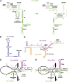
Figure 1
Figure 1
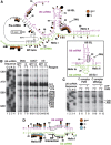
RNA structures in the spliceosome. (A) Proposed alternative structures of the human U2 snRNA based on the models of the yeast U2 snRNA. (B) Structure of U5 snRNA. (C) Structure of the U4/U6 di-snRNA duplex. (D, E) Models for the step 1 catalytic centre according to Madhani and Guthrie (1992) and Sun and Manley (1995), respectively. The following colour code for the U snRNAs is used in all diagrams: green U2, magenta U6, black pre-mRNA, and blue U5. The solid boxes denote the snRNA Sm binding sites. Black boxes E1 and E2 are exon 1 and exon 2. Pre-mRNA intron is depicted by a black line. All sequences and nucleotide positions shown are from human and abbreviations for natural modifications are in Supplementary Figure S2.
Figure 2
Figure 2
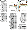
Nucleotide accessibility of U5 snRNA in spliceosomal complexes. (A) Chemical modification of the tri-snRNP (TSN) and B, Bact, and C complexes with the reagents indicated above the lanes (see text for details; KE: kethoxal). Modified bases were detected by primer extension analysis with an oligonucleotide complementary to U5 nts 83–103. See Supplementary Figure S2 for complete data set. Lanes to the right of a particular sequence were from a single gel; structural features of U5 are indicated on the right. (B) Summary of U5 base accessibilities observed in spliceosomal complexes. The colour code and the correlation of the dot sizes with reactivity are shown in the inset. Nucleotides upstream from the primer annealing site that do not bear labels were unreactive. Superscript m: 2′O-methyl. Source data for this figure is available on the online supplementary information page.
Figure 3
Figure 3
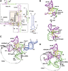
A 3-way junction is at the core of the human spliceosome. (A) Summary of nucleotide accessibilities determined by RNA structure probing of U2, U6, and the pre-mRNA in the core region of the Bact and C spliceosomal complexes. The degree of accessibility is indicated as in Figure 2B, and is superimposed on the RNA–RNA network of the C complex, drawn according to Madhani and Guthrie (1992); 3WJ: three-way junction. Inset: the four-way junction (4WJ) model (Sun and Manley, 1995); the critical CGC sequence that would be sequestered by base pairing according to this model is boxed. (B) Chemical modification of the 3′ end of U6 snRNA, analysed by primer extension (primer complementary to extra nucleotides added to the 3′ end of U6). Labels are as in Figure 2A. The DMS lanes are derived from an independent experiment, which was performed under identical conditions. RT stops corresponding to modified nucleotides in the single-stranded region between the 3′ end of U6 ISL and the beginning of U2/U6 helix II are indicated on the right. The CGC sequence (see inset in A) is boxed. Nucleotides U74 and A73 are labelled, as is the strong background stop corresponding to Gm2. (C) ATP-dependent DMS protection of C55 in U6. Purified C complexes formed on PM5 or MINXgg pre-mRNA were analysed as indicated. Complexes were treated with ATP (+) or left untreated (−) while still bound to the affinity column. After elution, they were immediately treated with DMS (+) or mock-treated (−). RNA was analysed by primer extension with an oligonucleotide complementary to U6 nts 80–100. Only the relevant portion of the sequencing gel is shown. (D) Summary of U2 and U6 protection in the proposed helix III region in the B, Bact, and C complexes. The original helix III spans U6 nts 30–42 and U2 nts 36–49. The ACAGA box of U6 is boxed. Source data for this figure is available on the online supplementary information page.
Figure 4
Figure 4
Remodelling of U2 stem-loop IIA between steps 1 and 2 of splicing. Base accessibility to CMCT (A) and DMS (B) of U2 nts U87–G97 in B and C complexes, analysed by primer extension with oligonucleotide K31 (complementary to U2 nts 149–169). (C) Summary of base accessibility of the U2 snRNA from the branchpoint binding region (thick bar) to the Sm binding site (starting at G98). Colour code as in Figure 2B. Solid line: sequences that would be involved in U2 helix III (hIII); shading: nucleotides that would be paired if helix IIC was formed (double-headed arrow). (DF) DMS, CMCT, and kethoxal (KE) modifications of the stem IIA region of U2 in B and C complexes. Critical nucleotides are shown on the right. The strong DMS modification of A66 that leads to stops at positions C67 and A66 (compare lane 6 with lanes 1 and 3) is likely due to gel compression that results in the A66 signal being split into two bands. A similar effect was observed at this position in the ddG sequencing lane 1 (see also Supplementary Figure S3B). Source data for this figure is available on the online supplementary information page.
Figure 5
Figure 5
Identification of RNA–RNA interactions via psoralen crosslinking. Northern blot analysis of psoralen-crosslinked RNA obtained from the B (A), Bact (B), and C (C) complexes. The panels with signals obtained from the 32P-labelled pre-mRNA (visualized directly), or probes against U5, U2, or U6 (indicated below) are displayed next to one another for each complex. All panels were derived from a single blot. Ps: psoralen; Pre: pre-mRNA; I, intron. Crosslinks are labelled to the right or left of the panels. Pre-mRNAs and first step intermediates are indicated on the left. The PM5–20 pre-mRNA used for Bact complex isolation is 68 nts shorter than the PM5 pre-mRNA used for the B and C complexes. The band labelled with an asterisk corresponds to a truncated pre-mRNA (∼7% of total) remaining in the C complex preparation that could not undergo the first step of splicing. (D) X, Y, and Z are regions excised from an equivalent gel and from which crosslinked species were extracted for further characterization (Figure 7). Source data for this figure is available on the online supplementary information page.
Figure 6
Figure 6
Mapping of C complex-specific psoralen crosslinks by site-specific RNase H cleavage. Total psoralen-crosslinked RNA from the C complex was incubated with RNase H and the oligonucleotides indicated above each lane (see C and D for their position), and the reaction products were subsequently identified by northern blotting. The origin of the signals is noted below the panels in (A) and (B), with ‘Pre-mRNA’ indicating the signal derived from the 32P-labelled pre-mRNA. (A) Mapping of crosslinks of U2 and U5 to the intron. The two intron species (intron long: IL and intron short: IS) that are present in the C complex are indicated. The likely structures of the main cleavage products are shown schematically, where a blue dot indicates crosslinked U5 snRNA and a green dot indicates crosslinked U2 snRNA. The location of the cleavage sites is indicated on the cleavage products, assuming that RNase H will cleave at most 3 nts away from the ends of a DNA/RNA duplex (Nowotny et al, 2005). (B) Mapping of snRNA–snRNA crosslinks. The asterisk denotes truncated pre-mRNA (see Figure 5). The double asterisks denote cleavage products from the U2/U6 helix II duplex and the arrow denotes the cleavage product from the U2/I/U5 crosslink. (C, D) The annealing positions of DNA oligonucleotides used for RNAse H mapping are indicated by thin lines. In (D), the position of the crosslinks, as determined by primer extension analysis (see Figure 7), is indicated by red bars. Source data for this figure is available on the online supplementary information page.
Figure 7
Figure 7
Mapping of psoralen-crosslinked nucleotides by reverse transcription. (AC) RNAs crosslinked in C complexes formed on the PM5 substrate were isolated from gel regions X, Y, and Z (see Figure 5D) as indicated above each lane, and analysed by reverse transcription with primers complementary to U5 nts 83–103 (A), U2 nts 77–97 (B), or U6 nts 80–100 (C). Ps: psoralen; the control was material isolated from an equivalent gel region from a non-crosslinked sample. Primer extension of RNA isolated from the U2 (in B) or U2/U6 (in C) region of a preparative gel (compare Figure 5). Labelled stops correspond to the crosslinked nucleotides. Source data for this figure is available on the online supplementary information page.
Figure 8
Figure 8
A model of the RNA network in the spliceosomal C complex. (A) RNA structural elements used in modelling. Intron positions start with +1. Thick-dotted lines: tertiary interactions taken from a group II intron (Michel et al, 2009; Keating et al, 2010); thin-dotted lines: modelled interactions; solid lines ending in boxes: stacking interactions. Yellow: the catalytic triad and residues implicated in magnesium binding (Fabrizio and Abelson, 1992; Yean et al, 2000); orange: 5′ ss, branchpoint, and last nucleotide of exon 1; arrows connect strands in a 5′ to 3′ direction. BABE: the +10 position used for site-directed hydroxyl-radical probing (Rhode et al, 2006). Rectangular light red box: nucleotides modelled on the core of the group II intron by homology. (B) Two views of the RNA spliceosomal core. Face-on view of the catalytic centre (top), and a rotation clockwise by 120° (bottom) to show the position of helix II. The boxed region from (A) is shown, together with the attached helix Ia. An arbitrary tetraloop sequence was used to close the U6 ISL. (C) Positioning of the ACAGA/5' ss and the branchpoint helix (BP) onto the core structure. See text for details. The most reasonable spatial positioning of U5 with the bound exon 1 is indicated by the arrow. The position of the PPY tract leading to exon 2 is schematically shown by the thick-dotted line (PPY/exon 2). (D) Positioning of the U2/U6 helix III region onto the core structure.
Figure 9
Figure 9
Docking of the RNA model onto the structure of the yeast Prp8 protein. (A) Structural overview of the Prp8 protein (Galej et al, 2013). (B) The landmarks used to dock the RNA model. The Aar2 protein and the Jab1/MPN domain are removed. (CE) The docked RNA model is shown on the solvent-accessible surface of the combined reverse transcriptase and endonuclease domains coloured according to their electrostatic potential (±3 kTe−1). Three orientations are shown: a face-on view (C) and rotations by 90° of this view to the right (D) or left (E). A movie animation is in Supplementary Data.

Comment in

  • RNAtomy of the Spliceosome's heart.
    Bonnal S, Valcárcel J. Bonnal S, et al. EMBO J. 2013 Oct 30;32(21):2785-7. doi: 10.1038/emboj.2013.213. Epub 2013 Sep 24. EMBO J. 2013. PMID: 24065126 Free PMC article.

References

    1. Baker NA, Sept D, Joseph S, Holst MJ, McCammon JA (2001) Electrostatics of nanosystems: application to microtubules and the ribosome. Proc Natl Acad Sci USA 98: 10037–10041 - PMC - PubMed
    1. Behzadnia N, Golas MM, Hartmuth K, Sander B, Kastner B, Deckert J, Dube P, Will CL, Urlaub H, Stark H, Lührmann R (2007) Composition and three-dimensional EM structure of double affinity-purified, human prespliceosomal A complexes. EMBO J 26: 1737–1748 - PMC - PubMed
    1. Berglund JA, Rosbash M, Schultz SC (2001) Crystal structure of a model branchpoint-U2 snRNA duplex containing bulged adenosines. RNA 7: 682–691 - PMC - PubMed
    1. Bessonov S, Anokhina M, Krasauskas A, Golas MM, Sander B, Will CL, Urlaub H, Stark H, Lührmann R (2010) Characterization of purified human Bact spliceosomal complexes reveals compositional and morphological changes during spliceosome activation and first step catalysis. RNA 16: 2384–2403 - PMC - PubMed
    1. Bessonov S, Anokhina M, Will CL, Urlaub H, Lührmann R (2008) Isolation of an active step I spliceosome and composition of its RNP core. Nature 452: 846–850 - PubMed

Publication types