. 2013 Dec;22(12):2770-6.
doi: 10.1007/s00586-013-2993-0. Epub 2013 Sep 5.

Deviation analysis of C2 translaminar screw placement assisted by a novel rapid prototyping drill template: a cadaveric study

Affiliations

Deviation analysis of C2 translaminar screw placement assisted by a novel rapid prototyping drill template: a cadaveric study

Yong Hu et al. Eur Spine J. 2013 Dec.

Abstract

Purpose: The goal of this study is to evaluate the accuracy of patient-specific CT-based rapid prototype drill templates for C2 translaminar screw insertion.

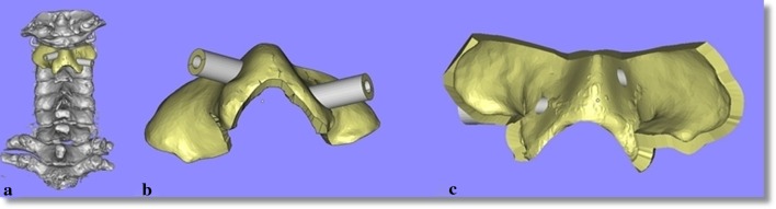
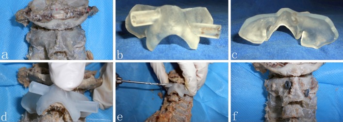
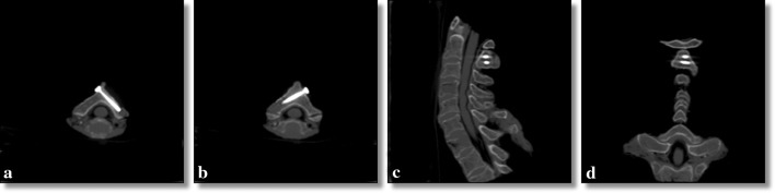
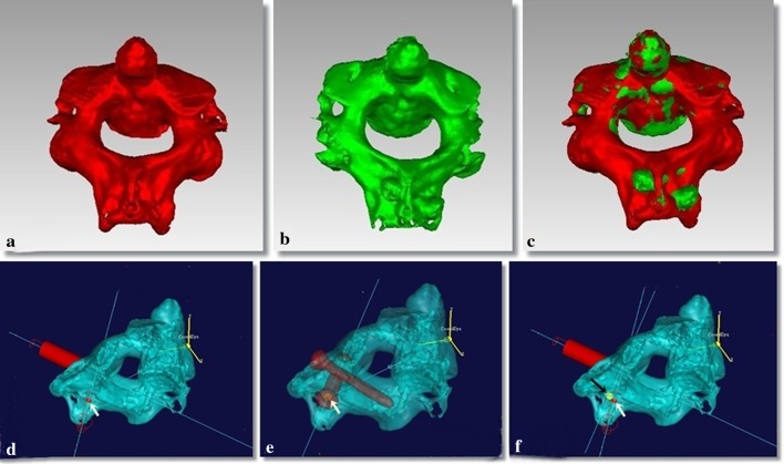
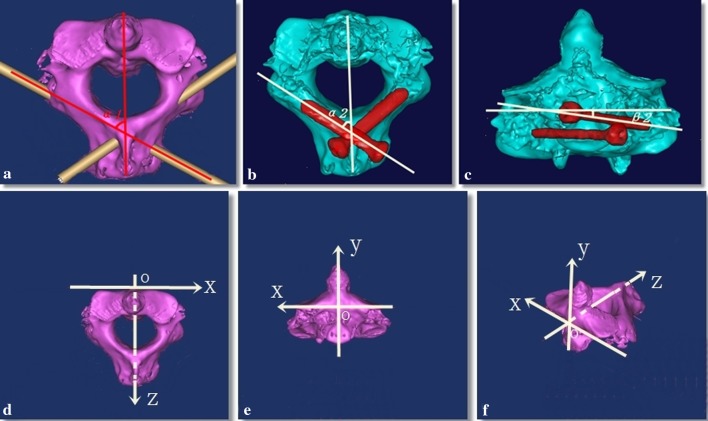
Methods: Volumetric CT scanning was performed in 32 cadaveric cervical spines. Using computer software, the authors constructed drill templates that fit onto the posterior surface of the C2 vertebrae with drill guides to match the slope of the patient's lamina. Thirty-two physical templates were created from the computer models using a rapid prototyping machine. The drill templates were used to guide drilling of the lamina and post-operative CT images were obtained. The entry point and direction of the planned and inserted screws were measured and compared.

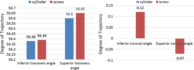
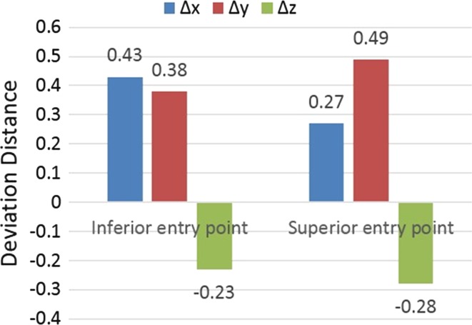
Results: Sixty-four C2 translaminar screws were placed without violating the cortical bone of a single lamina. The bilateral average transverse angle of intended and actual screw for C2TLS was 56.60 ± 2.22°, 56.38 ± 2.51°, 56.65 ± 2.24°, 56.39 ± 2.45°. The bilateral mean coronal angle of the planned and actual screw for C2TLS was 0°, 0°, -0.07 ± 0.32°, 0.12 ± 0.57°. The average displacement of the entry point of the superior and inferior C2TLS in the x, y, z axis was 0.27 ± 0.85, 0.49 ± 1.46, -0.28 ± 0.69, 0.43 ± 0.88, 0.38 ± 1.51, 0.23 ± 0.64 mm.

Conclusion: The small deviations seen are likely due to human error in the form of small variations in the surgical technique and use of software to design the prototype. This technology improves the safety profile of this fixation technique and should be further studied in clinical applications.


Figures

Fig. 1
Fig. 1
The 3D model of C2TLS drill template. The template on a vertebra (a), the dorsal aspect of the template (b), the ventral aspect of the template (c)
Fig. 2
Fig. 2
The application of the drill template. The posterior surface of atlantoaxial vertebrae with soft tissue removed (a), dorsal aspect of template (b), ventral aspect of template (c), the template on a vertebra (d), drill assisted by template (e), C2TLS fixed on C2 (f)
Fig. 3
Fig. 3
Post-operative CT images. Axial cuts in the plane of the translaminar screws (a, b), sagittal (c) and coronal (d) images
Fig. 4
Fig. 4
Geomagic studio images to evaluate the spatial position between pre- and post-operative images. The pre-operative image of C2 (a) and the post-operative image of C2 (b) are combined to reveal the spatial position between pre- and post-operative data (c). The entry point of the cylinder for C2TLS was marked by a red spot (d), the entry point of screw for C2TLS was marked by a yellow spot (e). The measurement of entry point data from planned to post-operative is shown (f)
Fig. 5
Fig. 5
Computer reconstructions revealing the measurement of the screw angles and the schematic diagram of the C2 space coordinates. The planned transverse angle of the cylinder for C2TLS (a). The planned transverse (b), and coronal (c) angles for placement of C2TLS. The defined C2 space coordinates (df)
Fig. 6
Fig. 6
Graph comparing the planned (cylinder) and actual (screw) angles of the translaminar screws revealing remarkable precision of screw placement
Fig. 7
Fig. 7
Graph illustrating the minimal deviation observed in the entry points of the translaminar screws in all three planes

References

    1. Bransford RJ, Russo AJ, Freeborn M, et al. Posterior C2 instrumentation: accuracy and complications associated with four techniques. Spine. 2011;36:E936–E943. doi: 10.1097/BRS.0b013e3181fdaf06. - DOI - PubMed
    1. Guo Q, Liu J, Ni B, et al. C2 laminar screw and C1–2 transarticular screw combined with C1 laminar hooks for atlantoaxial instability with unilateral vertebral artery injury. Arch Orthop Trauma Surg. 2011;131:1207–1210. doi: 10.1007/s00402-011-1277-6. - DOI - PubMed
    1. Hong JT, Yi JS, Kim JT, et al. Clinical and radiologic outcome of laminar screw at C2 and C7 for posterior instrumentation—review of 25 cases and comparison of C2 and C7 intralaminar screw fixation. World Neurosurg. 2010;73:112–118. doi: 10.1016/j.surneu.2009.06.010. - DOI - PubMed
    1. Lee SH, Kim ES, Sung JK, et al. Clinical and radiological comparison of treatment of atlantoaxial instability by posterior C1–C2 transarticular screw fixation or C1 lateral mass-C2 pedicle screw fixation. J Clin Neurosci. 2010;17:886–892. doi: 10.1016/j.jocn.2009.10.008. - DOI - PubMed
    1. Goel A, Laheri V. Plate and screw fixation for atlanto-axial subluxation. Acta Neurochir. 1994;129:47–53. doi: 10.1007/BF01400872. - DOI - PubMed

Publication types