

Fiducial marker-based correction for involuntary motion in weight-bearing C-arm CT scanning of knees. Part I. Numerical model-based optimization
- PMID: 24007156
- PMCID: PMC3751969
- DOI: 10.1118/1.4817476
Fiducial marker-based correction for involuntary motion in weight-bearing C-arm CT scanning of knees. Part I. Numerical model-based optimization
Abstract
Purpose: Human subjects in standing positions are apt to show much more involuntary motion than in supine positions. The authors aimed to simulate a complicated realistic lower body movement using the four-dimensional (4D) digital extended cardiac-torso (XCAT) phantom. The authors also investigated fiducial marker-based motion compensation methods in two-dimensional (2D) and three-dimensional (3D) space. The level of involuntary movement-induced artifacts and image quality improvement were investigated after applying each method.
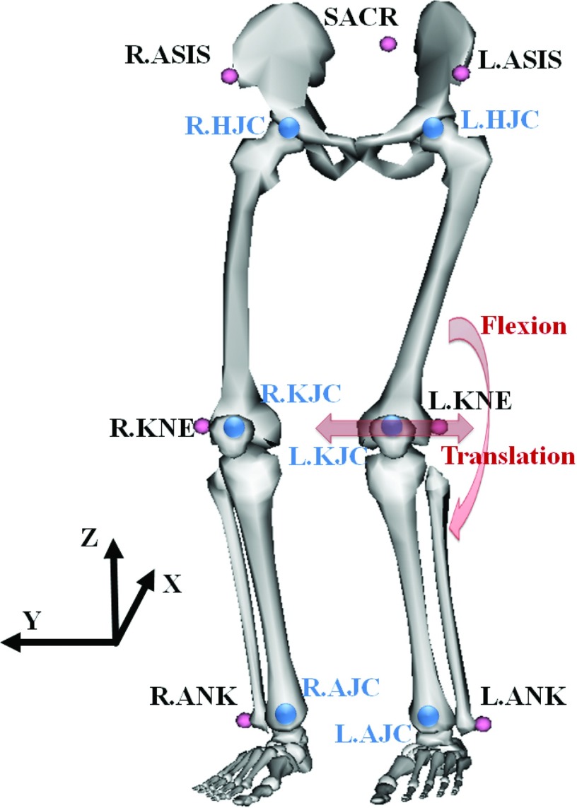
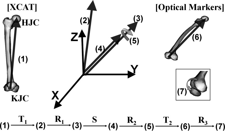
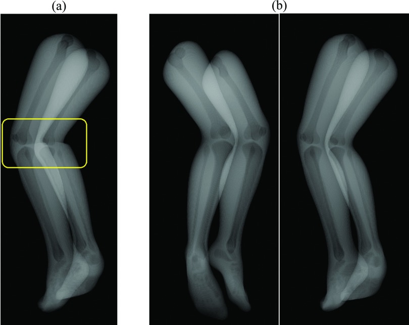
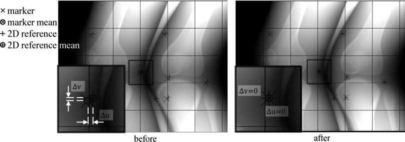
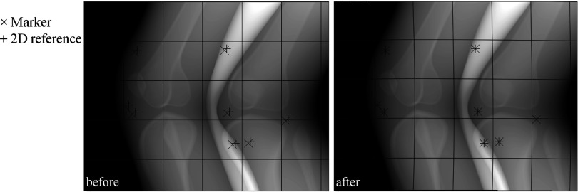
Methods: An optical tracking system with eight cameras and seven retroreflective markers enabled us to track involuntary motion of the lower body of nine healthy subjects holding a squat position at 60° of flexion. The XCAT-based knee model was developed using the 4D XCAT phantom and the optical tracking data acquired at 120 Hz. The authors divided the lower body in the XCAT into six parts and applied unique affine transforms to each so that the motion (6 degrees of freedom) could be synchronized with the optical markers' location at each time frame. The control points of the XCAT were tessellated into triangles and 248 projection images were created based on intersections of each ray and monochromatic absorption. The tracking data sets with the largest motion (Subject 2) and the smallest motion (Subject 5) among the nine data sets were used to animate the XCAT knee model. The authors defined eight skin control points well distributed around the knees as pseudo-fiducial markers which functioned as a reference in motion correction. Motion compensation was done in the following ways: (1) simple projection shifting in 2D, (2) deformable projection warping in 2D, and (3) rigid body warping in 3D. Graphics hardware accelerated filtered backprojection was implemented and combined with the three correction methods in order to speed up the simulation process. Correction fidelity was evaluated as a function of number of markers used (4-12) and marker distribution in three scenarios.
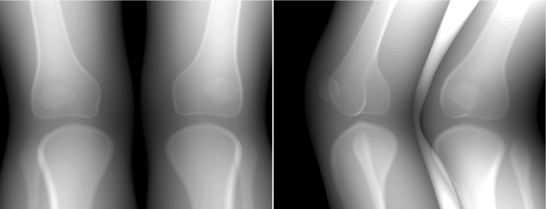
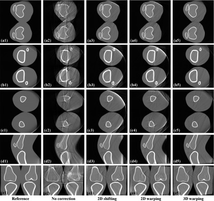
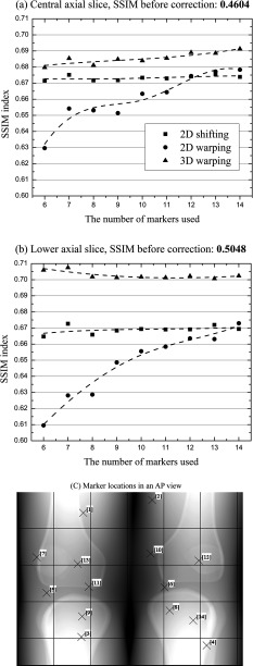
Results: Average optical-based translational motion for the nine subjects was 2.14 mm (± 0.69 mm) and 2.29 mm (± 0.63 mm) for the right and left knee, respectively. In the representative central slices of Subject 2, the authors observed 20.30%, 18.30%, and 22.02% improvements in the structural similarity (SSIM) index with 2D shifting, 2D warping, and 3D warping, respectively. The performance of 2D warping improved as the number of markers increased up to 12 while 2D shifting and 3D warping were insensitive to the number of markers used. The minimum required number of markers for 2D shifting, 2D warping, and 3D warping was 4-6, 12, and 8, respectively. An even distribution of markers over the entire field of view provided robust performance for all three correction methods.
Conclusions: The authors were able to simulate subject-specific realistic knee movement in weight-bearing positions. This study indicates that involuntary motion can seriously degrade the image quality. The proposed three methods were evaluated with the numerical knee model; 3D warping was shown to outperform the 2D methods. The methods are shown to significantly reduce motion artifacts if an appropriate marker setup is chosen.
Figures
References
-
- Maier A., Choi J.-H., Keil A., Niebler C., Sarmiento M., Fieselmann A., Gold G., Delp S., and Fahrig R., “Analysis of vertical and horizontal circular C-arm trajectories,” Proc. SPIE 7961, 796123–796128 (2011).10.1117/12.878502 - DOI
-
- Zbijewski W., De Jean P., Prakash P., Ding Y., Stayman J. W., Packard N., Senn R., Yang D., Yorkston J., Machado A., Carrino J. A., and Siewerdsen J. H., “A dedicated cone-beam CT system for musculoskeletal extremities imaging: Design, optimization, and initial performance characterization,” Med. Phys. 38(8), 4700–4713 (2011).10.1118/1.3611039 - DOI - PMC - PubMed
-
- Prümmer M., Wigstrom L., Hornegger J., Boese J., Lauritsch G., Strobel N., and Fahrig R., “Cardiac C-arm CT: Efficient motion correction for 4D-FBP,” IEEE Nucl. Sci. Symp. Conf. Rec. 4, 2620–2628 (2006).10.1109/NSSMIC.2006.354444 - DOI
Publication types
MeSH terms
Grants and funding
LinkOut - more resources
Full Text Sources
Other Literature Sources
Medical
