. 2013:4:2465.
doi: 10.1038/ncomms3465.

Role of the C-terminal domain in the structure and function of tetrameric sodium channels

Affiliations
Free PMC article

Role of the C-terminal domain in the structure and function of tetrameric sodium channels

Claire Bagnéris et al. Nat Commun. 2013.
Free PMC article

Abstract

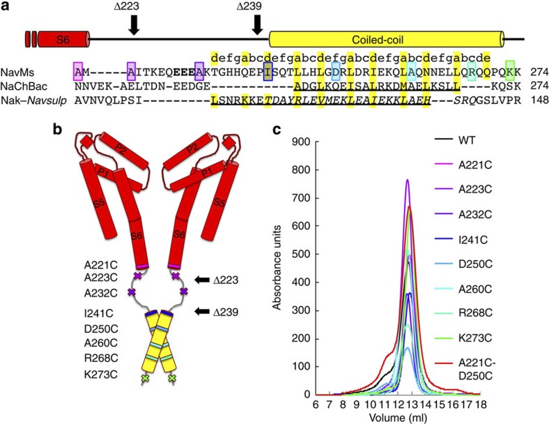
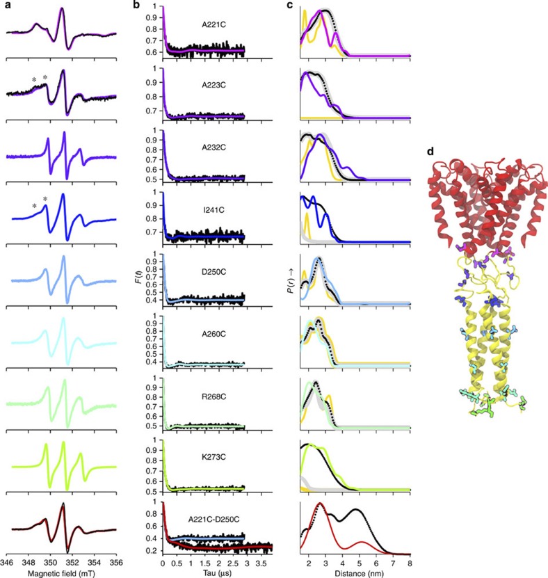
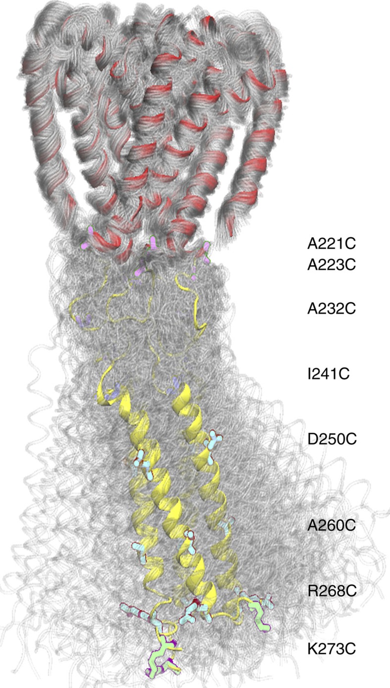
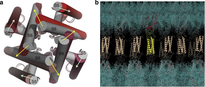
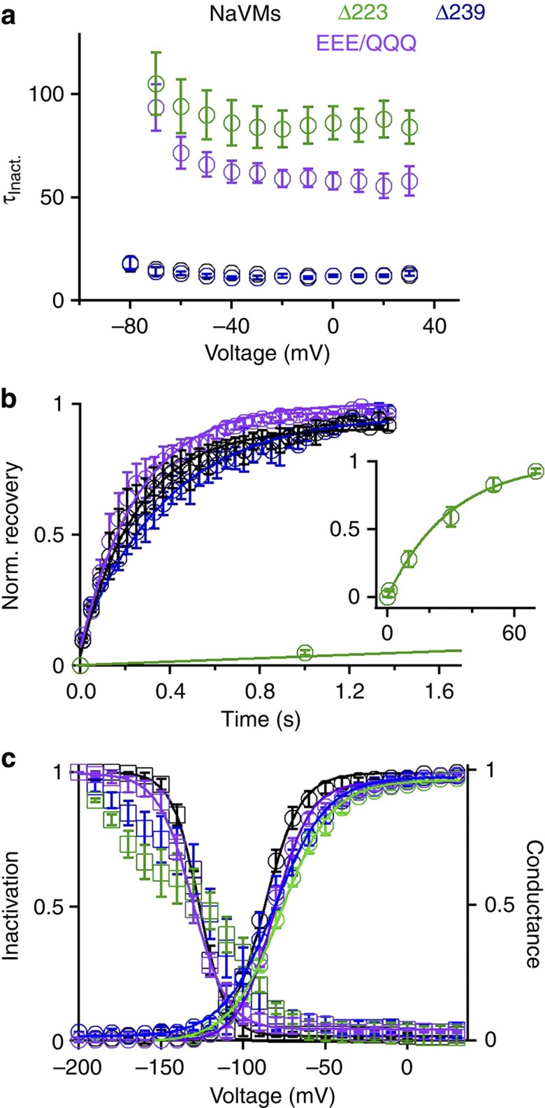
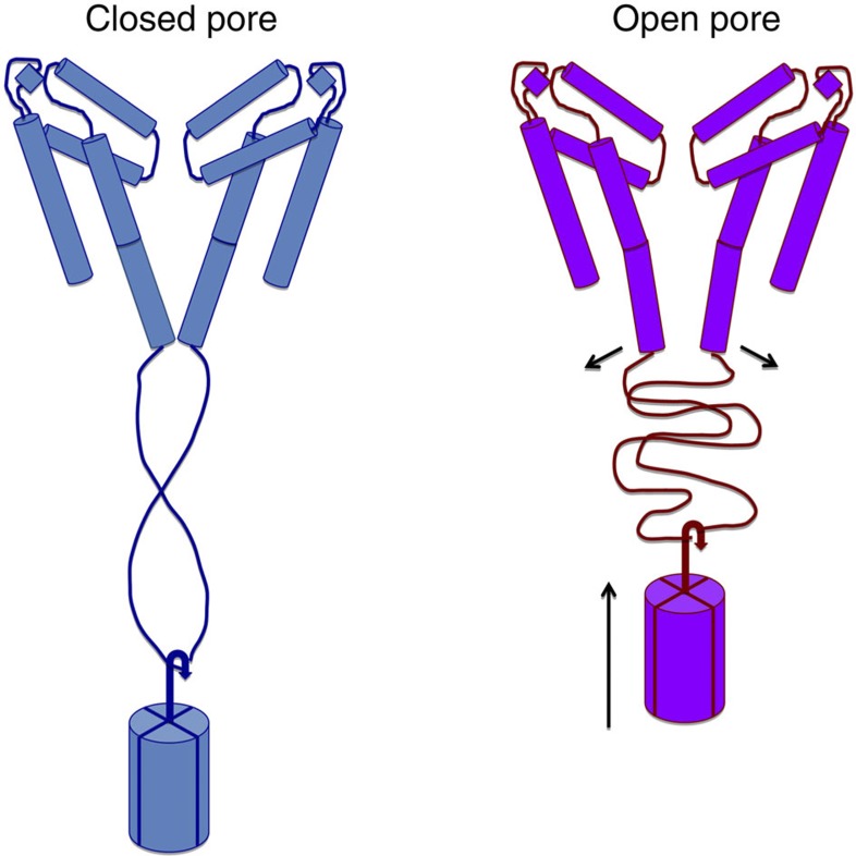
Voltage-gated sodium channels have essential roles in electrical signalling. Prokaryotic sodium channels are tetramers consisting of transmembrane (TM) voltage-sensing and pore domains, and a cytoplasmic carboxy-terminal domain. Previous crystal structures of bacterial sodium channels revealed the nature of their TM domains but not their C-terminal domains (CTDs). Here, using electron paramagnetic resonance (EPR) spectroscopy combined with molecular dynamics, we show that the CTD of the NavMs channel from Magnetococcus marinus includes a flexible region linking the TM domains to a four-helix coiled-coil bundle. A 2.9 Å resolution crystal structure of the NavMs pore indicates the position of the CTD, which is consistent with the EPR-derived structure. Functional analyses demonstrate that the coiled-coil domain couples inactivation with channel opening, and is enabled by negatively charged residues in the linker region. A mechanism for gating is proposed based on the structure, whereby splaying of the bottom of the pore is possible without requiring unravelling of the coiled-coil.


Figures

Figure 1
Figure 1. Labelled proteins.
(a) Alignment of the CTDs of bacterial sodium channels starting at the end of transmembrane helix S6 (red bar above alignment). GenBank nucleotide accession codes: NavMs, YP_864725; NaChBac, NP_242367; chimeric NaK-NavSulP, with NaK, AB617622 and (italicised) NavSulP, NAS-14.1, AALZ01000002. The coiled-coil region predicted for NavMs is indicated by a yellow bar above the sequence alignment. The residues in NaChBac, which form the helical region and the region of the NaK-NavSulP chimera, which forms a coiled-coil are underlined. Residues that were mutated to cysteines and spin labelled are in coloured boxes. The same colouring scheme for each mutant is used in all figures: transmembrane residue A221 is pink, linker region residues A223 and A232 are lilac and purple, respectively; residues I241, D250, A260 and R268 in the predicted coiled-coil region are shades of blue and the final residue K273 is green. The EEE residues changed in the QQQ mutant used for electrophysiology are in bold. (b) Model of the open pore channel, adapted from McCusker et al. showing the locations of the spin-labelled amino acids. The outward displacement of the end of transmembrane helix S6 in this open form is due to a kink at T209 in the middle of S6. Only two of the four monomers are shown for clarity. The black arrows indicate the positions of the truncations (Δ223 and Δ239) used in the electrophysiology experiments. (c) Size exclusion chromatography of wild-type and mutant proteins used in the EPR experiments, showing all run as well-behaved tetramers.
Figure 2
Figure 2. EPR spectroscopy.
(a) The first derivative absorption cw-EPR spectra of PROXYL spin-labelled detergent-solubilized NavMs constructs are depicted in coloured lines, with A221C and A223C spin-labelled mutants in a liposome environment overlaid (black lines) in the top two panels. Additional shoulders present in the low-field region for A223C and I241C are indicated by ‘*’. In the bottom panel, the spectrum of the A221C/D250C double mutant (red line) is compared to the 1:1 summation (black line) of the spectra of the A221C and D250C single mutants. Spectra were normalized to reflect approximately equal numbers of spins. (b) Background-corrected dipolar evolution data (black lines) and the fits to the DEER data obtained by Tikhonov regularization (coloured lines). (c) Distance distributions obtained by: Tikhonov regularization (different coloured lines for each mutant spectrum), except for the A221C–D250C double mutant (bottom panel) where two Rice distributions were used; MMM predictions based on the first static model structure are represented as orange lines and those based on the first dynamic model are thick grey lines; MMM predictions based on the final dynamic model are in black dotted lines. All plots are normalized by amplitude. (d) Three-dimensional structure of the NavMs transmembrane pore crystal structure with the CTD as determined by the DEER spectroscopy/molecular dynamics approach.
Figure 3
Figure 3. DEER-derived model showing the dynamics of the pore and CTD.
Individual structures from separate trajectories are overlaid to show the large motions in the CTD, clearly indicating why this region is not well ordered in the crystal electron density map. See also Supplementary Movie 1.
Figure 4
Figure 4. Crystal structure of the NavMs-pore+CTD.
(a) The tetrameric pore structure of NavMs-pore+CTD is in fully open conformation (depicted in cylinder mode, with each monomer in a different shade of red), overlaid for comparison on the closed channel pore structure of the NavAb orthologue (grey). Yellow arrows show the direction of the movement of the end of S6, and light green arrows the movement of the base of S5, between the closed and open pores. (b) Compatibility of the DEER-derived CTD structure with the crystal structure/packing. Electron density map (in blue) overlaid by the structure (in ribbon representation) of the pore domain, with the DEER-defined CTD structure fit into the ‘disordered’ region between ordered tetramers in the crystal lattice. For clarity, one tetramer is depicted with its pore domain in red and its CTD in yellow; the others are in cream.
Figure 5
Figure 5. Inactivation properties of wild-type NavMs and truncated and mutant channels in Sf9 cells.
(a) Time constants of inactivation of the NavMs channels measured from depolarizing voltages from a holding potential of −200 mV. τinact was measured by fitting the decay of current during a 100 or 500 ms depolarization to a single exponential equation. In all panels of this figure, wild-type channel results are shown in black, Δ223 construct in green, Δ239 construct in blue and the EEE to QQQ mutant in purple (error bars=s.e.m.; n=4–8 cells). (b) Rate of recovery from inactivation. Sodium currents were completely inactivated by a 100 or 500 ms depolarization to −30 mV. The membrane potential was then held at −200 mV for varying time intervals; recovery was assessed by a second depolarization to −30 mV. The proportion of second to the first depolarization is the normalized recovery from inactivation (n=4). (Inset) The rate of complete recovery of the Δ223 mutant required a longer time scale (70 s). (c) Voltage dependence of activation and inactivation. The steady-state inactivation was assessed by a depolarization to −30 mV after 100 or 500 ms voltage steps. The corresponding conductance was calculated as current divided by voltage (I/V). The resulting conductance–voltage and inactivation–voltage relationships were fit to a sigmoid equation. The voltage dependence of inactivation data of the Δ223 and Δ239 truncations did not converge on a sigmoid relation (error bars=s.e.m.; n=4 cells).
Figure 6
Figure 6. Schematic model for the role of the CTD in gating.
The helices in the TM domain are depicted as cylinders, with the break in the middle of the S6 cylinder located at the threonine hinge that produces the difference between open and closed pore structures. Only two monomers of the tetramer are shown for clarity. As an aid to visualisation of extended and relaxed states, the tetrameric coiled-coil at the distal end of the CTD is depicted as a mass on the end of a ‘spring’ formed by the flexible linker region, which can change conformation (without breaking hydrogen bonds) to accommodate the differences in spacing of the ends of the open and closed states.

Similar articles

Cited by

References

    1. Hille B. Ionic Channels of Excitable Membranes Sinauer Associates Inc.: Sunderland, MA, (2001).
    1. Noda M. et al. Expression of functional sodium channels from cloned cDNA. Nature 322, 826–828 (1986). - PubMed
    1. Charalambous K. & Wallace B. A. NaChBac: the long lost sodium channel ancestor. Biochemistry 50, 6742–6752 (2011). - PMC - PubMed
    1. Nurani G. et al. Tetrameric bacterial sodium channels: characterization of structure, stability, and drug binding. Biochemistry 47, 8114–8121 (2008). - PubMed
    1. Powl A. M., O'Reilly A. O., Miles A. J. & Wallace B. A. Synchrotron radiation circular dichroism spectroscopy-defined structure of the C-terminal domain of NaChBac and its role in channel assembly. Proc. Natl Acad. Sci. USA 107, 14064–14069 (2010). - PMC - PubMed

Publication types

MeSH terms

LinkOut - more resources