

Attenuation correction for flexible magnetic resonance coils in combined magnetic resonance/positron emission tomography imaging
- PMID: 24056110
- PMCID: PMC4011564
- DOI: 10.1097/RLI.0b013e3182a530f8
Attenuation correction for flexible magnetic resonance coils in combined magnetic resonance/positron emission tomography imaging
Abstract
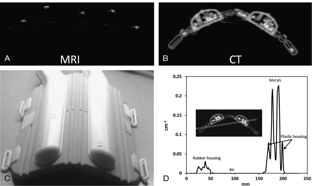
Introduction: Attenuation correction for magnetic resonance (MR) coils is a new challenge that came about with the development of combined MR and positron emission tomography (PET) imaging. This task is difficult because such coils are not directly visible on either PET or MR acquisitions with current combined scanners and are therefore not easily localized in the field of view. This issue becomes more evident when trying to localize flexible MR coils (eg, cardiac or body matrix coil) that change position and shape from patient to patient and from one imaging session to another. In this study, we proposed a novel method to localize and correct for the attenuation and scatter of a flexible MR cardiac coil, using MR fiducial markers placed on the surface of the coil to allow for accurate registration of a template computed tomography (CT)-based attenuation map.
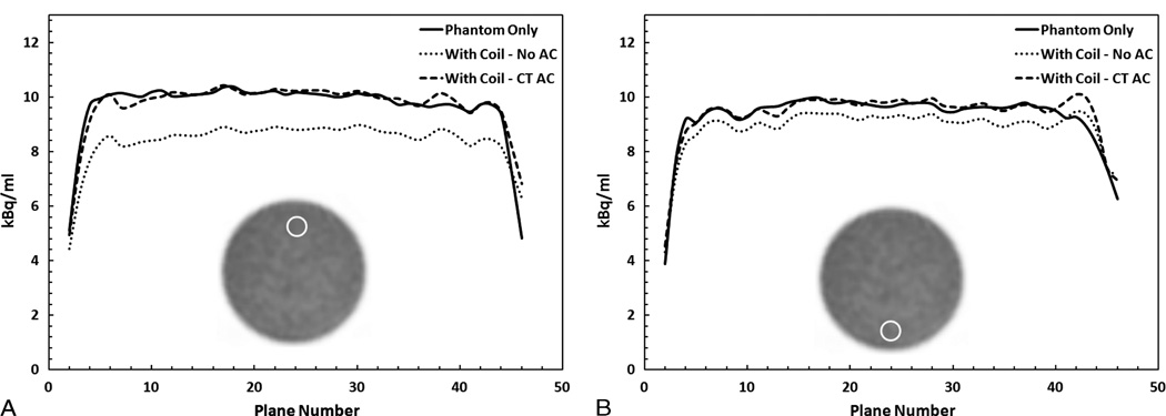
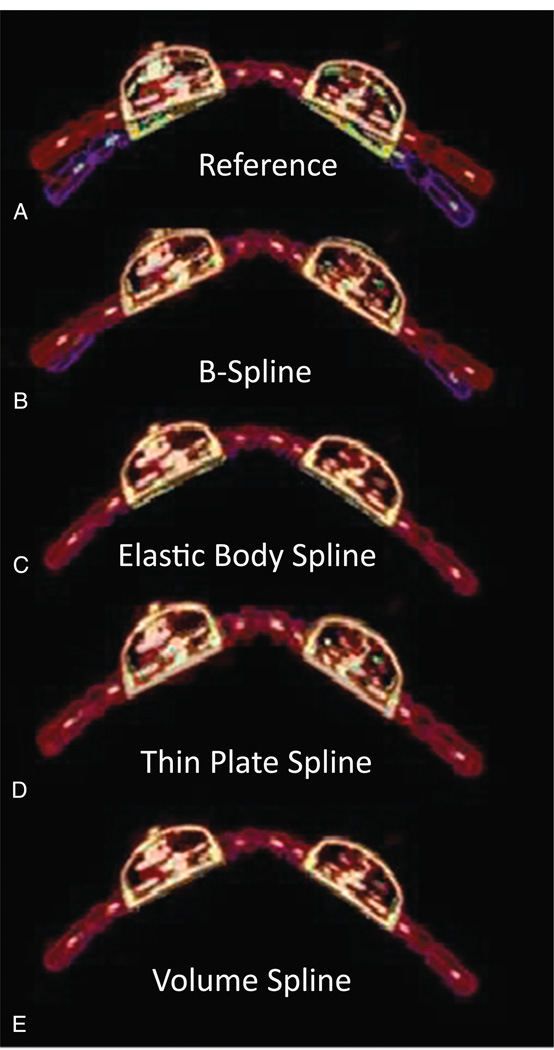
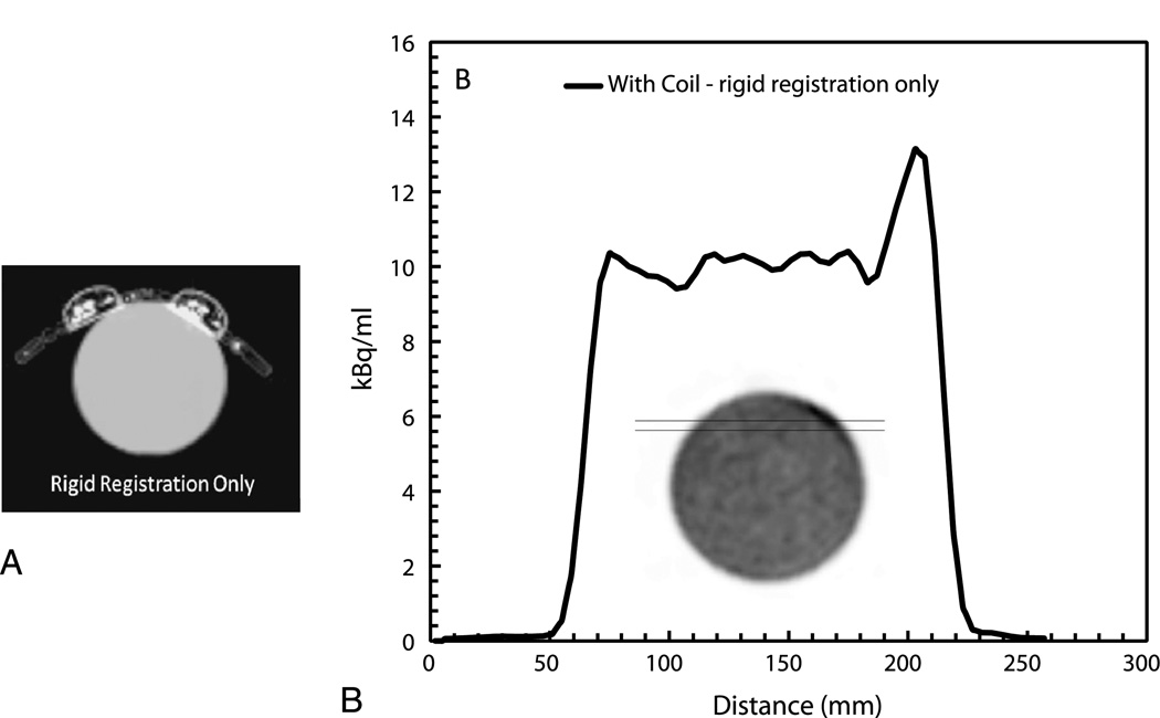
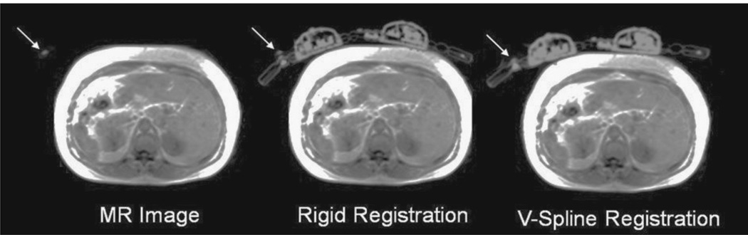
Materials and methods: To quantify the attenuation properties of the cardiac coil, a uniform cylindrical water phantom injected with 18F-fluorodeoxyglucose (18F-FDG) was imaged on a sequential MR/PET system with and without the flexible cardiac coil. After establishing the need to correct for the attenuation of the coil, we tested the feasibility of several methods to register a precomputed attenuation map to correct for the attenuation. To accomplish this, MR and CT visible markers were placed on the surface of the cardiac flexible coil. Using only the markers as a driver for registration, the CT image was registered to the reference image through a combination of rigid and deformable registration. The accuracy of several methods was compared for the deformable registration, including B-spline, thin-plate spline, elastic body spline, and volume spline. Finally, we validated our novel approach both in phantom and patient studies.
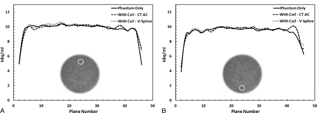
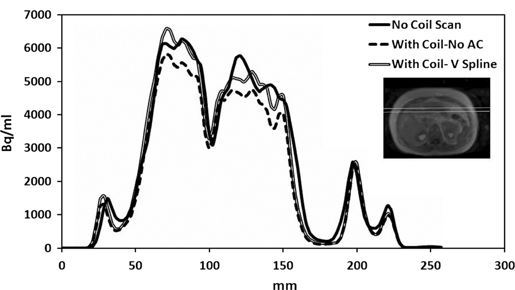
Results: The findings from the phantom experiments indicated that the presence of the coil resulted in a 10% reduction in measured 18F-FDG activity when compared with the phantom-only scan. Local underestimation reached 22% in regions of interest close to the coil. Various registration methods were tested, and the volume spline was deemed to be the most accurate, as measured by the Dice similarity metric. The results of our phantom experiments showed that the bias in the 18F-FDG quantification introduced by the presence of the coil could be reduced by using our registration method. An overestimation of only 1.9% of the overall activity for the phantom scan with the coil attenuation map was measured when compared with the baseline phantom scan without coil. A local overestimation of less than 3% was observed in the ROI analysis when using the proposed method to correct for the attenuation of the flexible cardiac coil. Quantitative results from the patient study agreed well with the phantom findings.
Conclusions: We presented and validated an accurate method to localize and register a CT-based attenuation map to correct for the attenuation and scatter of flexible MR coils. This method may be translated to clinical use to produce quantitatively accurate measurements with the use of flexible MR coils during MR/PET imaging.
Conflict of interest statement
Conflict of interest
The authors report no conflicts of interest.
Figures
References
-
- Shao Y, Cherry SR, Farahani K, et al. Simultaneous PET and MR imaging. Phys Med Biol. 1997;42:1965–1970. - PubMed
-
- Schlemmer HP, Pichler BJ, Schmand M, et al. Simultaneous MR/PET imaging of the human brain: feasibility study. Radiology. 2008;248:1028–1035. - PubMed
-
- Delso G, Furst S, Jakoby B, et al. Performance measurements of the Siemens mMR integrated whole-body PET/MR scanner. J Nucl Med. 2011;52:1914–1922. - PubMed
Publication types
MeSH terms
Grants and funding
LinkOut - more resources
Full Text Sources
Other Literature Sources
Medical
