. 2013:531:61-90.
doi: 10.1016/B978-0-12-407863-5.00004-6.

Optofluidic cell selection from complex microbial communities for single-genome analysis

Affiliations

Optofluidic cell selection from complex microbial communities for single-genome analysis

Zachary C Landry et al. Methods Enzymol. 2013.

Abstract

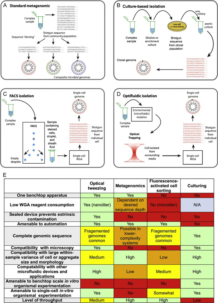
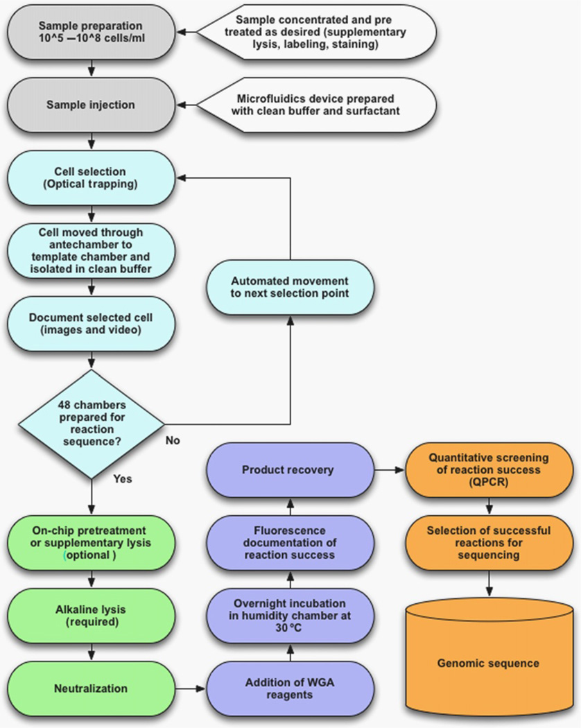
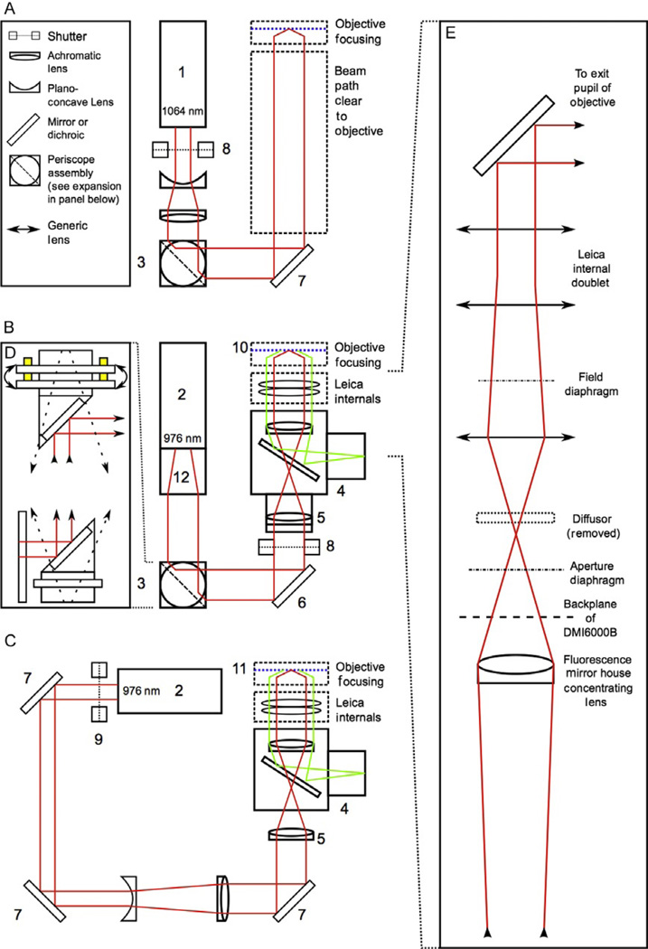
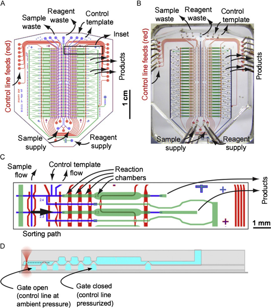
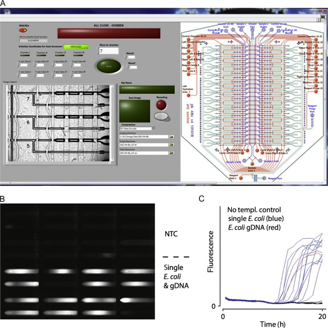
Genetic analysis of single cells is emerging as a powerful approach for studies of heterogeneous cell populations. Indeed, the notion of homogeneous cell populations is receding as approaches to resolve genetic and phenotypic variation between single cells are applied throughout the life sciences. A key step in single-cell genomic analysis today is the physical isolation of individual cells from heterogeneous populations, particularly microbial populations, which often exhibit high diversity. Here, we detail the construction and use of instrumentation for optical trapping inside microfluidic devices to select individual cells for analysis by methods including nucleic acid sequencing. This approach has unique advantages for analyses of rare community members, cells with irregular morphologies, small quantity samples, and studies that employ advanced optical microscopy.

Keywords: Contamination; Lab-on-a-chip; Laser; Microfluidic device; Multiple displacement amplification; Nanoliter; Optical tweezer; Single amplified genome; Single-cell sequencing; Whole-genome amplification.


Figures

Figure 4.1
Figure 4.1
Schematic diagram contrasting of methods to obtain genome sequences from yet-uncultured microbial species. Established techniques such as metagenomics (A) or culturing (B), and the two newer methods of single-cell whole-genome amplification by fluorescence-activated cell sorting (C), or the optofluidic approach discussed in this chapter (D). Advantages and features of each methodology are summarized in the table (E). Parts A–D were adapted with permission from Blainey (2013), FEMS Microbiology Reviews 2013.
Figure 4.2
Figure 4.2
Flowchart for single-cell whole-genome amplification optofluidics. Sample preparation and cell selection steps are shown in white; lysis-related steps are shown in light gray; amplification and product recovery are shown in dark gray; postprocessing steps are shown in black.
Figure 4.3
Figure 4.3
Simplified schematic diagrams showing an idealized light path for an inverted microscope with a minimum of internal components (schematic A), and two functional designs based around the Leica DMI6000B microscope stand (schematics B and C). The suggested design in schematic A includes a 1064-nm, 3-W laser source (1) chosen for its high power and ready availability, as well as its wavelength, which is suitable for biological materials. The idealized design contains a beam expander consisting of a set of matched lenses preceded by a shutter (8; a Thorlabs part no. SH05 with a SC10 shutter controller was used in the configuration shown in B) placed at the head of the laser to enable control the beam without cycling the laser. Beam positioning and alignment is accomplished with a periscope consisting of two rotating mirrors mounted at 90 °C angles. An expanded view of the periscope used in the second configuration is presented in inset D (3; Thorlabs part no. RS99, equipped with dielectric broadband mirrors, Thorlabs part no. BB1-E03). By placing the periscope mirrors at right angles to each other, rotation of the mirrors can be used to coarsely position the beam horizontally and vertically on the third mirror, eliminating the need for three independent kinematic mounts. The periscope design used includes kinematic controls on the top mirror mount, allowing for the fine pitch-and-yaw adjustments needed for positioning at the second mirror. A third kinematic mount (6; Thorlabs part no. KM100 kinematic mount with BB1-E03 mirror) is used to adjust beam angle. The two designs utilizing the Leica DMI6000B microscope stand are somewhat more complex, largely due to the number of internal optics in the scope stand. Both of these setups utilized a 1.0–1.1-W, 976-nm laser (Crystalaser model DL-980-1W-OX/DL980-1W; 2), the wavelength chosen because of biological compatibility. The laser in the schematic B was modified at the factory with a spatial filter (12) to improve beam shape and power distribution. This spatial filter had the added effect of expanding the beam to ~8 mm, eliminating the need for additional beam expander optics. This design uses a periscope for two of the mirrors as described above. A third kinematic mount provides correction for beam angle (6). In this design, the shutter (8) is mounted outside of a customized mirror house (4) that includes a dichroic mirror to allow for simultaneous trapping and fluorescence. Due to the mirror house optics designed to bring the fluorescence excitation source into wide illumination field at the focal plane, a corrective achromatic lens (5) was installed in the mirror house at the factory to correct expansion of the trapping beam so that the beam would remain collimated upon entering the exit pupil of the trapping objective. This design utilized a 100 × magnification, 1.4 numerical aperture (NA) apochromatic oil immersion objective as the trapping objective (10; Leica part no. 11504107). An alternative design shown in schematic C was also used. This design uses an independent corrective lens in the free space laser setup to offset the fluorescence optics and also includes a free space Galilean beam expander made from two matching lenses located between the second and third kinematic mounts. In this setup, the laser was mounted at a height and three individual generic mirrors and kinematic mounts (7) were used to align the laser. As in the suggested setup, a shutter (9; Uniblitz) was placed at the head of the laser. The trapping objective used here was 100 × magnification, 1.3 NA apochromatic oil objective (Leica part no. 11506197; 11). A simplified diagram of the Leica DMI6000B internal components (inset E) is shown in the expansion on the right of the figure. Because the optical design inside the microscope is Leica-proprietary, the exact specifications are not indicated here. The important feature to note is that expansion and focusing optics placed external to the scope stand must be positioned so as to produce a collimated beam at the end of the light path prior to entering the exit pupil of the trapping objective. An additional, important modification is removal of the standard diffuser included in the Leica excitation light path (see inset E). The diffuser is located on a circuit board inside the scope at the position marked in inset E. Modifications to the scope internals are exacting and more accurate diagrams of the light path and scope internals can be requested from the manufacturer.
Figure 4.4
Figure 4.4
48-chamber microfluidic chip for single cell sorting and whole-genome amplification. (A) Design of 48x_v4 device with key ports marked. (B) Photograph of 48-chamber device with corresponding ports marked. (C) Inset showing detail of two reaction chambers in the 48x_v4 device. (D) Cross-sectional schematic corresponding to part (C) indicating the trapping of a cell in the (upper) flow layer and the actuation of valves by pressurization of channels in the (lower) control layer.
Figure 4.5
Figure 4.5
Example of dual-screen graphical user interface with integrated microfluidic controls, stage automation, and video and image recording (A). Automated fluorescence data acquisition (B) and real-time kinetics curve of double-stranded DNA formation in individual microfluidic reaction chambers (C).

References

    1. Ashkin A. Forces of a single-beam gradient laser trap on a dielectric sphere in the ray optics regime. Biophysical Journal. 1992;61:569–582. - PMC - PubMed
    1. Ashkin A. Optical trapping and manipulation of neutral particles using lasers. Proceedings of the National Academy of Sciences of the United States of America. 1997;94:4853–4860. - PMC - PubMed
    1. Ashkin A, Dziedzic JM. Internal cell manipulation using infrared laser traps. Proceedings of the National Academy of Sciences of the United States of America. 1989;86:7914–7918. - PMC - PubMed
    1. Ashkin A, Dziedzic JM, Yamane T. Optical trapping and manipulation of single cells using infrared laser beams. Nature. 1987;330:769–771. - PubMed
    1. Ashkin A, Gordon JP. Stability of radiation-pressure particle traps: An optical Earnshaw theorem. Optics Letters. 1983;8:511–513. - PubMed

Publication types

MeSH terms