

Magnetic resonance imaging evaluation after implantation of a titanium cervical disc prosthesis: a comparison of 1.5 and 3 Tesla magnet strength
- PMID: 24061966
- PMCID: PMC3804698
- DOI: 10.1007/s00586-013-2994-z
Magnetic resonance imaging evaluation after implantation of a titanium cervical disc prosthesis: a comparison of 1.5 and 3 Tesla magnet strength
Abstract
Purpose: Cervical disc prostheses induce significant amount of artifact in magnetic resonance imaging which may complicate radiologic follow-up after surgery. The purpose of this study was to investigate as to what extent the artifact, induced by the frequently used Discover(®) cervical disc prosthesis, impedes interpretation of the MR images at operated and adjacent levels in 1.5 and 3 Tesla MR.
Methods: Ten subsequent patients were investigated in both 1.5 and 3 Tesla MR with standard image sequences one year following anterior cervical discectomy with arthroplasty.
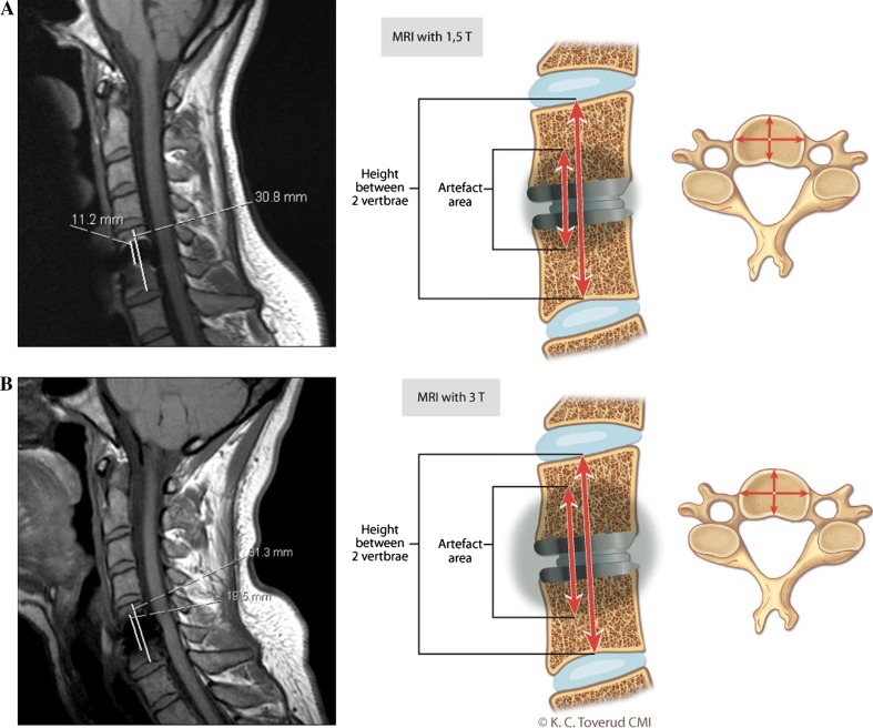
Outcome measures: Two neuroradiologists evaluated the images by consensus. Emphasis was made on signal changes in medulla at all levels and visualization of root canals at operated and adjacent levels. A "blur artifact ratio" was calculated and defined as the height of the artifact on T1 sagittal images related to the operated level.
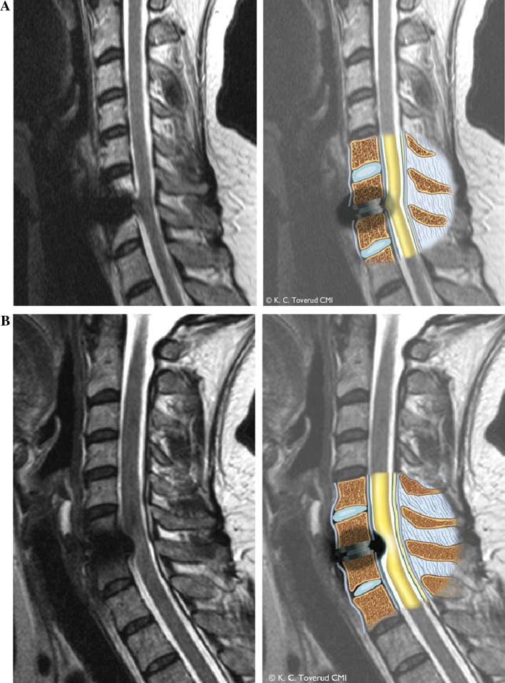
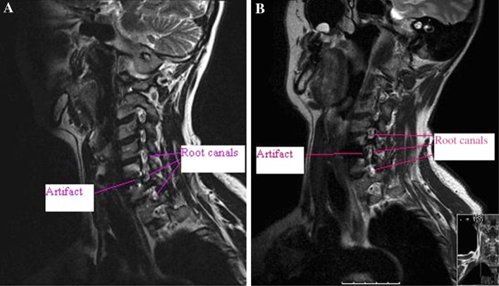
Results: The artifacts induced in 1.5 and 3 Tesla MR were of entirely different character and evaluation of the spinal cord at operated level was impossible in both magnets. Artifacts also made the root canals difficult to assess at operated level and more pronounced in the 3 Tesla MR. At the adjacent levels however, the spinal cord and root canals were completely visualized in all patients. The "blur artifact" induced at operated level was also more pronounced in the 3 Tesla MR.
Conclusions: The artifact induced by the Discover(®) titanium disc prosthesis in both 1.5 and 3 Tesla MR, makes interpretation of the spinal cord impossible and visualization of the root canals difficult at operated level. Adjusting the MR sequences to produce the least amount of artifact is important.
Figures
Similar articles
-
Magnetic resonance imaging evaluation of adjacent segments after cervical disc arthroplasty: magnet strength and its effect on image quality. Clinical article.J Neurosurg Spine. 2010 Dec;13(6):722-6. doi: 10.3171/2010.5.SPINE09721. J Neurosurg Spine. 2010. PMID: 21121749
-
Magnetic resonance imaging artifact following anterior cervical discectomy and fusion with a trabecular metal cage.J Neurosurg Spine. 2016 Mar;24(3):496-501. doi: 10.3171/2015.5.SPINE14219. Epub 2015 Nov 27. J Neurosurg Spine. 2016. PMID: 26613279
-
Magnetic resonance imaging clarity of the Bryan, Prodisc-C, Prestige LP, and PCM cervical arthroplasty devices.Spine (Phila Pa 1976). 2007 Mar 15;32(6):673-80. doi: 10.1097/01.brs.0000257547.17822.14. Spine (Phila Pa 1976). 2007. PMID: 17413473 Clinical Trial.
-
Reoperation After Cervical Disc Arthroplasty Versus Anterior Cervical Discectomy and Fusion: A Meta-analysis.Clin Orthop Relat Res. 2016 May;474(5):1307-16. doi: 10.1007/s11999-016-4707-5. Epub 2016 Feb 1. Clin Orthop Relat Res. 2016. PMID: 26831475 Free PMC article. Review.
-
Minimum four-year subsequent surgery rates of cervical disc replacement versus fusion: A meta-analysis of prospective randomized clinical trials.Orthop Traumatol Surg Res. 2017 Feb;103(1):45-51. doi: 10.1016/j.otsr.2016.10.008. Epub 2016 Nov 24. Orthop Traumatol Surg Res. 2017. PMID: 27890691 Review.
Cited by
-
Utilization of CT scanning associated with complex spine surgery.BMC Musculoskelet Disord. 2017 Jan 31;18(1):52. doi: 10.1186/s12891-017-1420-9. BMC Musculoskelet Disord. 2017. PMID: 28143506 Free PMC article.
-
Multiacquisition with variable resonance image combination T2 (MAVRIC SL T2) for postoperative cervical spine with artificial disc replacement.Sci Rep. 2022 Nov 9;12(1):19060. doi: 10.1038/s41598-022-23358-8. Sci Rep. 2022. PMID: 36352246 Free PMC article.
-
Postoperative MRI Visualization of the Cervical Spine Following Cervical Disc Arthroplasty: A Prospective Single-Center Comparison of a Titanium and Cobalt-Chromium Prosthesis.Global Spine J. 2023 Jan;13(1):67-73. doi: 10.1177/2192568221991105. Epub 2021 Jan 28. Global Spine J. 2023. PMID: 33504201 Free PMC article.
-
Artifacts in magnetic resonance imaging.Pol J Radiol. 2015 Feb 23;80:93-106. doi: 10.12659/PJR.892628. eCollection 2015. Pol J Radiol. 2015. PMID: 25745524 Free PMC article. Review.
-
An Artificial PVA-BC Composite That Mimics the Biomechanical Properties and Structure of a Natural Intervertebral Disc.Materials (Basel). 2022 Feb 16;15(4):1481. doi: 10.3390/ma15041481. Materials (Basel). 2022. PMID: 35208022 Free PMC article.
References
-
- Gore DR, Sepic SB (1984) Anterior cervical fusion for degenerated or protruded discs. A review of one hundred forty-six patients. Spine (Phila Pa 1976) 9: 667–671 - PubMed
-
- Robinson RA, Smith GW. Anterolateral cervical disc removal and interbody fusion for cervical disc syndrome. Bull Johns Hopkins Hosp. 1955;96:223–224.
-
- Smith GV, Robinson RA. The treatment of certain cervical-spine disorders by anterior removal of the intervertebral disc and interbody fusion. J Bone Joint Surg Am. 1958;40:607–624. - PubMed
Publication types
MeSH terms
Substances
LinkOut - more resources
Full Text Sources
Other Literature Sources
Medical
Molecular Biology Databases
