. 2013 Nov;86(1031):20130326.
doi: 10.1259/bjr.20130326.

Effects of ventricular insertion sites on rotational motion of left ventricular segments studied by cardiac MR

Affiliations

Effects of ventricular insertion sites on rotational motion of left ventricular segments studied by cardiac MR

I Codreanu et al. Br J Radiol. 2013 Nov.

Abstract

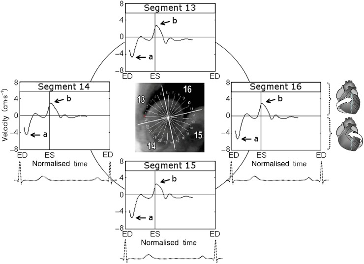
Objective: Obtaining new details for rotational motion of left ventricular (LV) segments using velocity encoding cardiac MR and correlating the regional motion patterns to LV insertion sites.

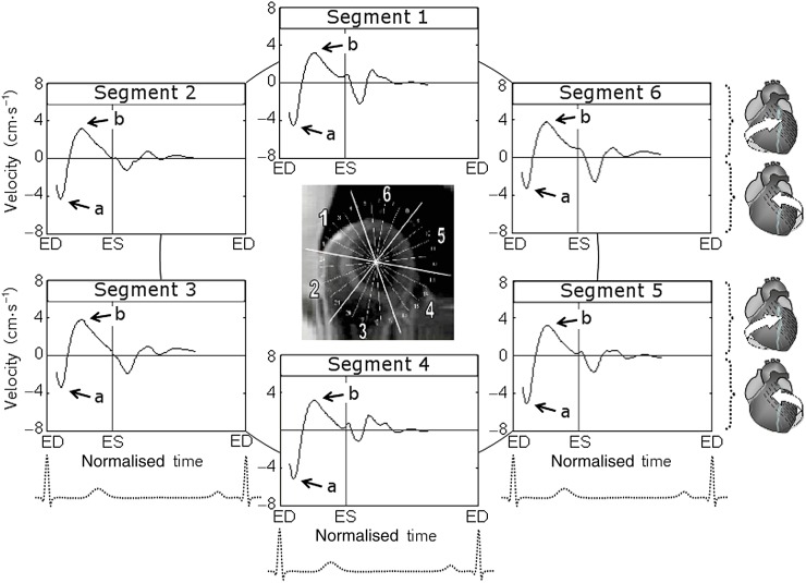
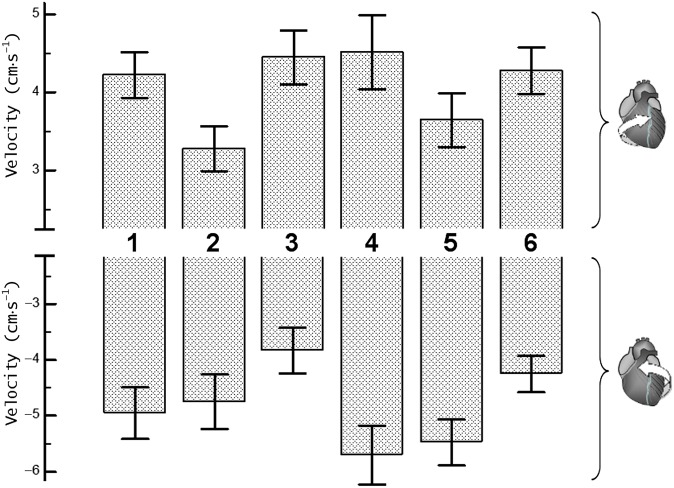
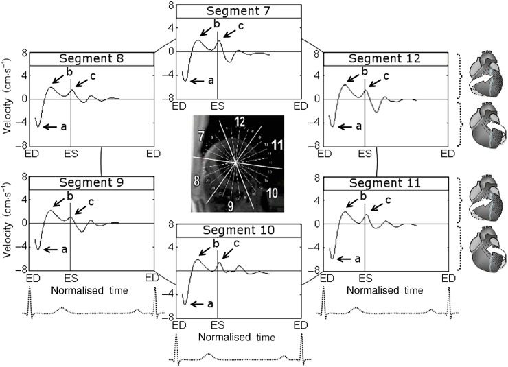
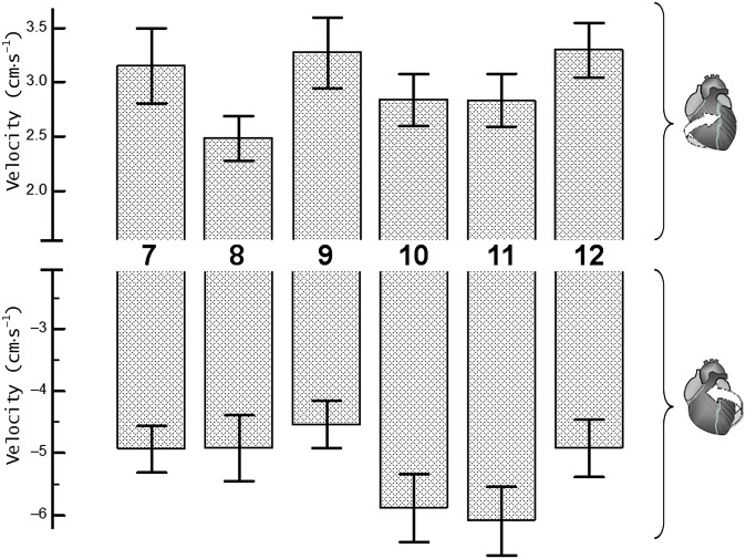
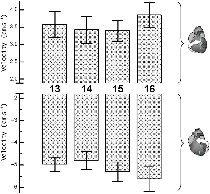
Methods: Cardiac MR examinations were performed on 14 healthy volunteers aged between 19 and 26 years. Peak rotational velocities and circumferential velocity curves were obtained for 16 ventricular segments.

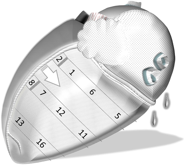
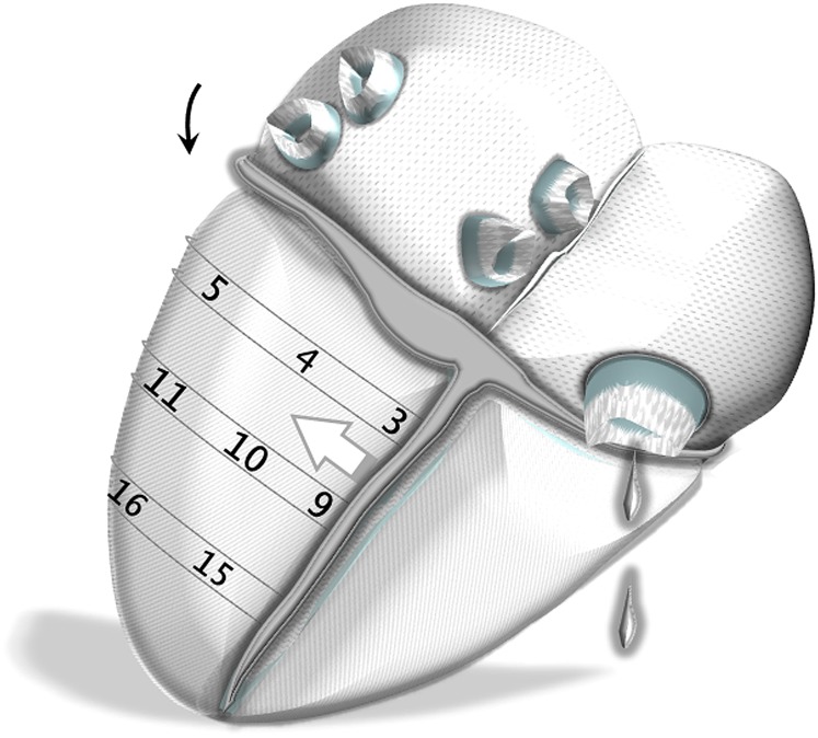
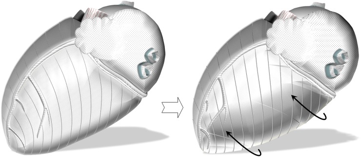
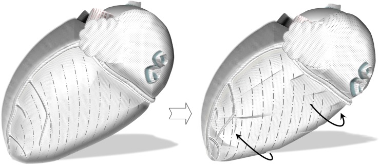
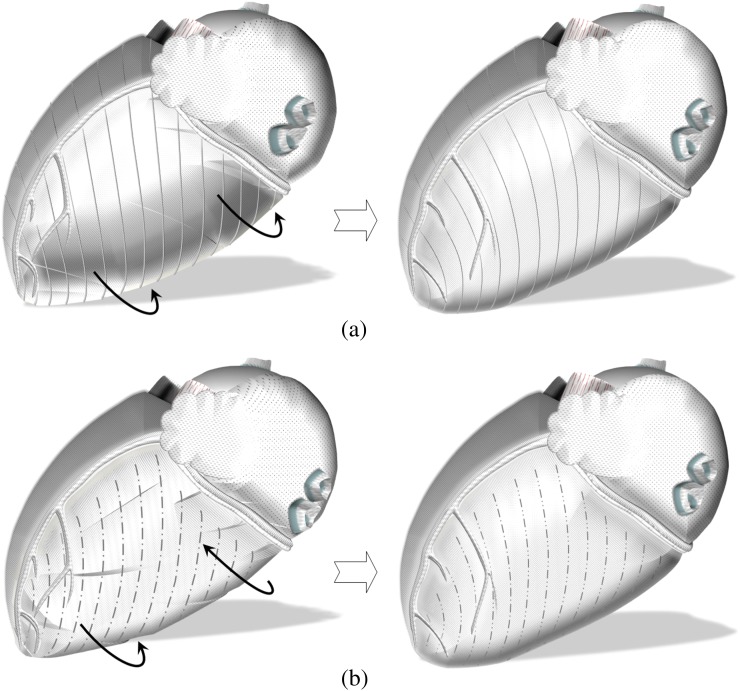
Results: Reduced peak clockwise velocities of anteroseptal segments (i.e. Segments 2 and 8) and peak counterclockwise velocities of inferoseptal segments (i.e. Segments 3 and 9) were the most prominent findings. The observations can be attributed to the LV insertion sites into the right ventricle, limiting the clockwise rotation of anteroseptal LV segments and the counterclockwise rotation of inferoseptal segments as viewed from the apex. Relatively lower clockwise velocities of Segment 5 and counterclockwise velocities of Segment 6 were also noted, suggesting a cardiac fixation point between these two segments, which is in close proximity to the lateral LV wall.

Conclusion: Apart from showing different rotational patterns of LV base, mid ventricle and apex, the study showed significant differences in the rotational velocities of individual LV segments. Correlating regional wall motion with known orientation of myocardial aggregates has also provided new insights into the mechanisms of LV rotational motions during a cardiac cycle.

Advances in knowledge: LV insertion into the right ventricle limits the clockwise rotation of anteroseptal LV segments and the counterclockwise rotation of inferoseptal segments adjacent to the ventricular insertion sites. The pattern should be differentiated from wall motion abnormalities in cardiac pathology.


Figures

Figure 1.
Figure 1.
Circumferential velocity graphs for basal left ventricular (LV) segments during a cardiac cycle. The graphs represent average myocardial velocities for all volunteers. Positive values correspond to clockwise rotation of the left ventricle as viewed from the apex, whereas negative values reflect counterclockwise motion. The arrows show peak counterclockwise (a) and peak clockwise (b) velocities. Segments: 1, basal anterior segment; 2, basal anteroseptal segment; 3, basal inferoseptal segment; 4, basal inferior segment; 5, basal inferolateral segment; and 6, basal anterolateral segment. ED, end diastole; ES, end systole.
Figure 2.
Figure 2.
Peak clockwise and peak counterclockwise velocities for basal left ventricular (LV) segments. The upper panel shows peak clockwise velocities and the lower panel shows peak counterclockwise velocities. Segments: 1, basal anterior segment; 2, basal anteroseptal segment; 3, basal inferoseptal segment; 4, basal inferior segment; 5, basal inferolateral segment; and 6, basal anterolateral segment.
Figure 3.
Figure 3.
Circumferential velocity graphs for mid-left ventricular (LV) segments during a cardiac cycle. The graphs represent the average myocardial velocities for all volunteers. Positive values correspond to clockwise rotation of the left ventricle as viewed from the apex, whereas negative values reflect counterclockwise motion. The arrows (a) and (b) show peak counterclockwise and peak clockwise velocities, respectively. The arrow (c) points towards a smaller wave of clockwise velocity after repolarisation during ventricular untwisting. Segments: 7, mid-anterior segment; 8, mid-anteroseptal segment; 9, mid-inferoseptal segment; 10, mid-inferior segment; 11, mid-inferolateral segment; and 12, mid-anterolateral segment. ED, end diastole; ES, end systole.
Figure 4.
Figure 4.
Peak clockwise and peak counterclockwise velocities for left ventricular (LV) segments at mid-ventricular level. The upper panel shows peak clockwise velocities and the lower panel shows peak counterclockwise velocities. Segments: 7, mid-anterior segment; 8, mid-anteroseptal segment; 9, mid inferoseptal segment; 10, mid-inferior segment; 11, mid-inferolateral segment; and 12, mid-anterolateral segment.
Figure 5.
Figure 5.
Circumferential velocity graphs for apical left ventricular (LV) segments during a cardiac cycle. The graphs represent the average myocardial velocities for all volunteers. Positive values correspond to clockwise rotation of the left ventricle as viewed from the apex, whereas negative values reflect counterclockwise motion. The arrows show peak counterclockwise (a) and peak clockwise (b) velocities. Segments: 13, apical anterior segment; 14, apical septal segment; 15, apical inferior segment; and 16, apical lateral segment. ED, end diastole; ES, end systole.
Figure 6.
Figure 6.
Peak clockwise and peak counterclockwise velocities for apical left ventricular (LV) segments. The upper panel shows peak clockwise velocities and the lower panel shows peak counterclockwise velocities. Segments: 13, apical anterior segment; 14, apical septal segment; 15, apical inferior segment; 16, apical lateral segment.
Figure 7.
Figure 7.
Schematic representation of left ventricular (LV) segments on the left lateral heart surface. Anteriorly, the LV insertion into the right ventricle is likely to affect the clockwise rotation of anteroseptal segments (white arrow). This can explain the lower peak clockwise velocities of Segments 2 and 8. Segments: 1, basal anterior segment; 2, basal anteroseptal segment; 5, basal inferolateral segment; 6, basal anterolateral segment; 7, mid-anterior segment; 8, mid-anteroseptal segment; 11, mid-inferolateral segment; 12, mid-anterolateral segment; 13, apical anterior segment; and 16, apical lateral segment.
Figure 8.
Figure 8.
Schematic representation of LV segments on the posterior heart surface. Posteriorly, the left ventricular (LV) insertion into the right ventricle is likely to affect the counterclockwise rotation of inferoseptal segments (white arrow). This can explain the lower peak counterclockwise velocities of Segments 3 and 9. In addition, the relatively lower clockwise velocity of Segment 5 in association with lower counterclockwise velocity of Segment 6 is rather suggestive of a cardiac fixation point between these two segments (curved black arrow), limiting the velocity of the motion away from this point. Potential causes might be supporting structures connecting the basal part of the left ventricle to the annulus (i.e. basal or tertiary cords), which are found in significant numbers in this region beneath the posterior leaflet of the mitral valve. Segments: 3, basal inferoseptal segment; 4, basal inferior segment; 5, basal inferolateral segment; 9, mid-inferoseptal segment; 10, mid-inferior segment; 11, mid-inferolateral segment; 15, apical inferior segment; and 16, apical lateral segment.
Figure 9.
Figure 9.
Schematic representation of the outer-surface myocardial aggregates extending to the right ventricle, great vessels and fibrous structures. Having the longest extension onto the anterior heart surface, a greater radius of curvature and greater moment of torque, they are likely to determine the dominant direction of initial ventricular rotation [13,23], causing the entire left ventricle to rotate in a counterclockwise direction as viewed from the apex (curved black arrows). As the range of rotational motion close to the left ventricular (LV) base insertion line is limited, the initial countercklockwise rotation of the LV base in synchrony with the rest of the ventricle swiftly comes to an end, facilitating LV twisting.
Figure 10.
Figure 10.
Schematic representation of the outer-surface myocardial aggregates with their extension limited to the left ventricular (LV) wall. Having a spiral orientation, they are expected to cause a rotational motion of the LV apex and base against each other (i.e. a clockwise rotation of the LV base and a counterclockwise rotation of the apex as shown by the curved black arrows), resulting in ventricular twisting. Because these aggregates are shorter, net motion only becomes apparent after the initial counterclockwise rotation of the entire left ventricle [13], which is dominated by the longer aggregates described in Figure 9.
Figure 11.
Figure 11.
Counterrotational motions after repolarisation. The relaxation of the outer-surface aggregates extending outside the left ventricle is expected to result in a clockwise rotation of the entire left ventricle, which is opposite to the systolic motion (a, curved black arrows). Relaxation of the outer-surface aggregates that are limited to the left ventricular (LV) wall is expected to result in a clockwise rotation of the apex and a counterclockwise rotation of the base (b, curved black arrows). The net result for the apical segments was a sudden change in rotational motion, which reflected in a prominent wave of clockwise rotation on velocity graphs (Figure 5, wave b). On the LV base, however, the motions counteracted each other—the velocity graphs showing gradual deceleration of the clockwise rotation immediately after repolarisation and a subsequent smaller wave of recoil counterclockwise motion in diastole (Figure 1).

Similar articles

Cited by

References

    1. Gustafsson U, Lindqvist P, Morner S, Waldenstrom A. Assessment of regional rotation patterns improves the understanding of the systolic and diastolic left ventricular function: an echocardiographic speckle-tracking study in healthy individuals. Eur J Echocardiogr 2009;10:56–61 10.1093/ejechocard/jen141 - DOI - PubMed
    1. Song J, Li C, Tong C, Yang H, Yang X, Zhang J, et al. Evaluation of left ventricular rotation and twist using speckle tracking imaging in patients with atrial septal defect. J Huazhong Univ Sci Technolog Med Sci. 2008;28:190–3 10.1007/s11596-008-0219-1 - DOI - PubMed
    1. Maier SE, Fischer SE, McKinnon GC, Hess OM, Krayenbuehl HP, Boesiger P. Evaluation of left ventricular segmental wall motion in hypertrophic cardiomyopathy with myocardial tagging. Circulation 1992;86:1919–28 - PubMed
    1. Kroeker CA, Tyberg JV, Beyar R. Effects of ischemia on left ventricular apex rotation. An experimental study in anesthetized dogs. Circulation 1995;92:3539–48 - PubMed
    1. Davidsen ES, Moen CA, Matre K. Radial deformation by tissue Doppler imaging in multiple myocardial layers. Scand Cardiovasc J 2010;44:82–91 10.1080/14017430903177708 - DOI - PubMed

Publication types