. 2013 Nov 5;110(45):18076-80.
doi: 10.1073/pnas.1317226110. Epub 2013 Oct 21.

Gate-tunable carbon nanotube-MoS2 heterojunction p-n diode

Affiliations

Gate-tunable carbon nanotube-MoS2 heterojunction p-n diode

Deep Jariwala et al. Proc Natl Acad Sci U S A. .

Abstract

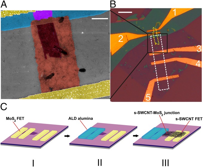
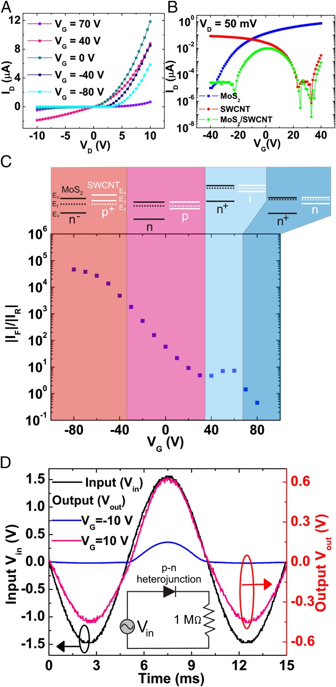
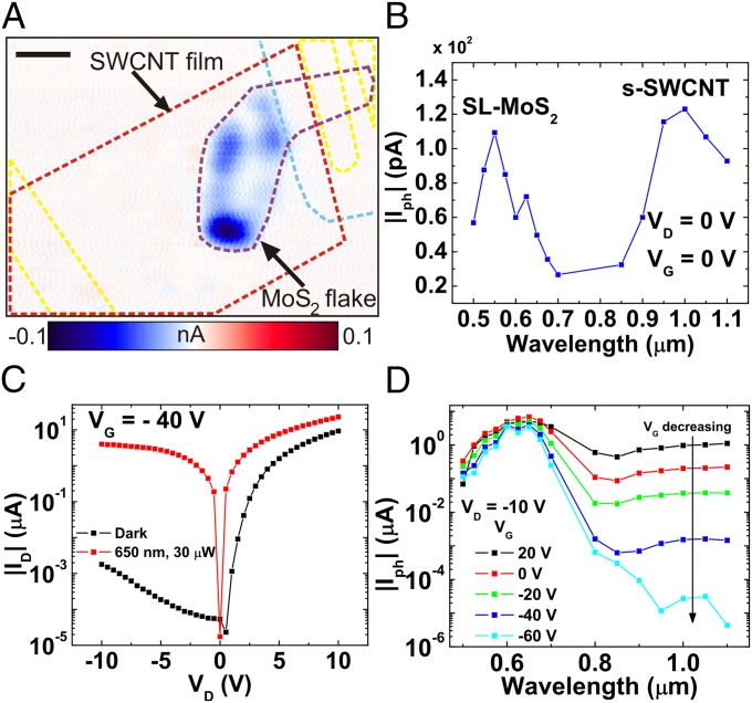
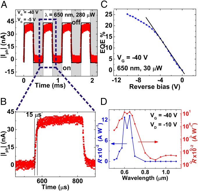
The p-n junction diode and field-effect transistor are the two most ubiquitous building blocks of modern electronics and optoelectronics. In recent years, the emergence of reduced dimensionality materials has suggested that these components can be scaled down to atomic thicknesses. Although high-performance field-effect devices have been achieved from monolayered materials and their heterostructures, a p-n heterojunction diode derived from ultrathin materials is notably absent and constrains the fabrication of complex electronic and optoelectronic circuits. Here we demonstrate a gate-tunable p-n heterojunction diode using semiconducting single-walled carbon nanotubes (SWCNTs) and single-layer molybdenum disulfide as p-type and n-type semiconductors, respectively. The vertical stacking of these two direct band gap semiconductors forms a heterojunction with electrical characteristics that can be tuned with an applied gate bias to achieve a wide range of charge transport behavior ranging from insulating to rectifying with forward-to-reverse bias current ratios exceeding 10(4). This heterojunction diode also responds strongly to optical irradiation with an external quantum efficiency of 25% and fast photoresponse <15 μs. Because SWCNTs have a diverse range of electrical properties as a function of chirality and an increasing number of atomically thin 2D nanomaterials are being isolated, the gate-tunable p-n heterojunction concept presented here should be widely generalizable to realize diverse ultrathin, high-performance electronics and optoelectronics.

Keywords: 2D transition metal dichalcogenide; photodetector; rectifier; single layer MoS2; van der Waals heterostructure.


Conflict of interest statement

The authors declare no conflict of interest.

Figures

Fig. 1.
Fig. 1.
Microscopy and fabrication of the s-SWCNTs/SL-MoS2 p-n heterojunction diode. (A) False-colored SEM image of the heterojunction diode. (Scale bar, 2.5 μm.) The yellow regions at the top and bottom are the gold electrodes. The patterned alumina (blue region) serves as a mask for insulating a portion of the SL-MoS2 flake (violet region). The pink region is the patterned random network of s-SWCNTs (p-type) in direct contact with the exposed part of the SL-MoS2 flake (n-type) to form the p-n heterojunction diode (dark red). (B) Optical micrograph showing the device layout at a lower magnification. The dashed yellow boundary indicates the SL-MoS2 flake, whereas the dashed white rectangle denotes the patterned s-SWCNT film. Electrodes 1 and 2 form the n-type (SL-MoS2) FET, which is insulated by the patterned alumina film (cyan). Electrodes 2–3 form the p-n heterojunction, whereas 3–4 and 4–5 form p-type s-SWCNT FETs. (Scale bar, 10 μm.) (C) Schematic of the fabrication process: (I) SL-MoS2 FET and an extra pair of electrodes are fabricated via e- beam lithography on 300 nm SiO2/Si. The Si substrate acts as the global back gate. (II) The MoS2 FET is insulated by patterning an alumina film in a liftoff process, followed by (III) transfer and patterning of the s-SWCNT network to yield the final device configuration consisting of a top contact SL-MoS2 FET, bottom contact s-SWCNT FET, and p-n heterojunction.
Fig. 2.
Fig. 2.
Electrical properties of the s-SWCNT/SL-MoS2 p-n heterojunction diode. (A) Gate-tunable output characteristics showing the transition from a nearly insulating state at VG = 70 V to a conductive state with relatively poor rectification at VG = 40 V to a highly rectifying diode behavior at negative gate voltages. (B) Transfer characteristics of the p-n junction (green), showing an antiambipolar characteristic, which is qualitatively a superposition of the transfer characteristics of the p-type s-SWCNT FET and n-type SL-MoS2 FET. (C) Forward-to-reverse current ratio (at a heterojunction bias magnitude of 10 V) as a function of gate bias. The labels at the top show the corresponding band diagrams for the s-SWCNT/SL-MoS2 p-n heterojunction. At a high positive gate bias, the formation of an n+-n junction implies a low rectification ratio that transitions into an n+-i junction (plateau region in the plot) with reducing VG. The rectification ratio then rises with decreasing gate bias due to the formation of a p-n junction. (D) Demonstration of gate-tunable rectification using the p-n heterojunction diode. The y axis on the left shows the input voltage, whereas the y axis on the right shows the output voltage across the series resistor (1 MΩ). As a function of the gate bias, the device evolves from a nonrectifying resistor-like state at VG = 10 V (magenta) to a diode-like rectifying state at VG = -10 V (blue).
Fig. 3.
Fig. 3.
Photoresponse of the p-n heterojunction. (A) Scanning photocurrent micrograph of a representative heterojunction device acquired at VD (s-SWCNT electrode), VG = 0 V showing the outlines of the SL-MoS2 flake (purple dashed line) and the patterned s-SWCNT film (red dashed line) acquired at 700 nm with 20-μW power. Regions of large negative photocurrent (blue) are observed in the overlapping junction region. The patterned alumina and electrodes are indicated by cyan and yellow dashed lines, respectively. (B) Photocurrent spectrum of the junction under global illumination and zero bias conditions. The photocurrent magnitude is highest at the characteristic absorption energies of both SL-MoS2 and s-SWCNTs. The photocurrent spectrum is acquired at the same incident power (30 μW). (C) Output curve of the same device in the dark and under global illumination at 650 nm. (D) Photocurrent spectral response can be tuned with the gate voltage. With decreasing gate voltage, the increased p-doping of the nanotubes and concomitant decreased n-doping of MoS2 leads to a lower photocurrent in the near infrared region.
Fig. 4.
Fig. 4.
Photodetection using the p-n heterojunction diode. (A and B) Time-dependent photoresponse of the p-n heterojunction showing fast rise and decay times of ∼15 μs. (C) EQE as a function of reverse bias for the heterojunction at 650 nm. EQE increases linearly with reverse bias from 0 to −5 V with the highest EQE of 25% occurring at −10 V. (D) Spectrally dependent responsivity (R) of the photodiode in linear (blue) and logarithmic (red) scales. A large responsivity is observed for the absorption wavelengths of SL-MoS2 compared with s-SWCNTs because the diode is being operated at VG = −40 V (depletion mode of SL-MoS2).

References

    1. Schwierz F. Graphene transistors. Nat Nanotechnol. 2010;5(7):487–496. - PubMed
    1. Jariwala D, Sangwan VK, Lauhon LJ, Marks TJ, Hersam MC. Carbon nanomaterials for electronics, optoelectronics, photovoltaics, and sensing. Chem Soc Rev. 2013;42(7):2824–2860. - PubMed
    1. Banerjee SK, et al. Graphene for CMOS and beyond CMOS applications. Proc IEEE. 2010;98(12):2032–2046.
    1. Britnell L, et al. Field-effect tunneling transistor based on vertical graphene heterostructures. Science. 2012;335(6071):947–950. - PubMed
    1. Georgiou T, et al. Vertical field-effect transistor based on graphene-WS2 heterostructures for flexible and transparent electronics. Nat Nanotechnol. 2013;8(2):100–103. - PubMed

Publication types