

doi: 10.3390/s131013584.
Design and development of a low-cost optical current sensor
Affiliations
- PMID: 24152922
- PMCID: PMC3859080
- DOI: 10.3390/s131013584
Item in Clipboard
Design and development of a low-cost optical current sensor
Sensors (Basel).
.
Abstract
In this paper we demonstrate the design of a low-cost optical current sensor. The sensor principle is the Faraday rotation of a light beam through a magneto-optical material, SF2, when a magnetic field is present. The prototype has a high sensitivity and a high linearity for currents ranging from 0 up to 800 A. The error of the optical fibre sensor is smaller than 1% for electric currents over 175 A.
Figures

Faraday rotation.
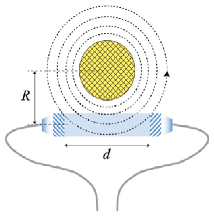
Geometry of our design showing the magnetic field generated by a metallic wire (yellow) around the SF2 glass rod (blue).

(a) Schematic representation of the optical head of the low-cost current sensor. L1, L2: collimating lenses; POL: polarizer; ROD: magnetooptical rod; ANA: analyser; PD: optical photodetector. (b) Close-up view of the magnetooptical rod.
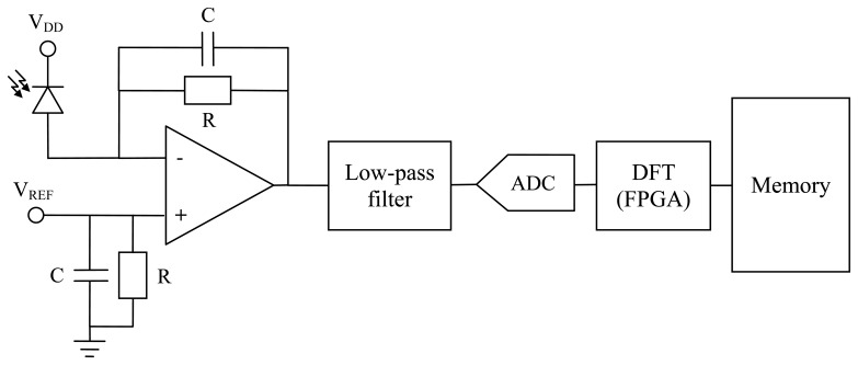
Electronic set-up for the acquisition of the optical current sensor signals.

Custom electronic hardware for the acquisition of the current sensor signals.
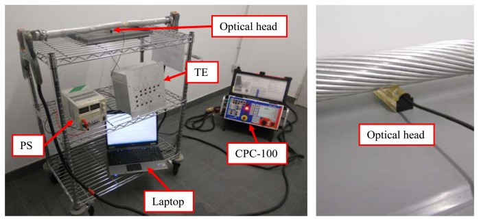
Test set-up of the low-cost optical current sensor (Left). Optical head detail (Right). TE: test equipment, including the electronic hardware for the acquisition inside. PS: power supply. Laptop: used to acquire all the data. Optical head: optical head of the current sensor.
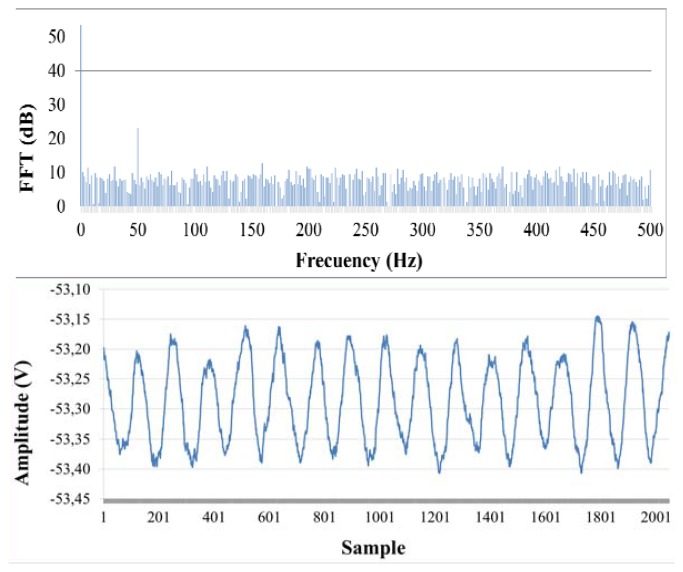
Optical signal received after amplification for I = 400 A (Above). DFT of the optical signal from 0 to 500 Hz (Below).
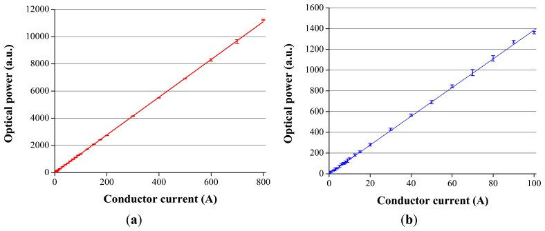
(a) 50 Hz component of the normalized DFT from I = 0 A to I = 800 A. (b) 50 Hz component of the normalized DFT from I = 0 A to I = 100 A.
References
-
- COSI-CTF3Flexible Optical Current Transformer. [(accessed on 19 May 2013)]. Available online: http://www.nxtphase.com/products-nxctf3.php.
-
- MOCT-Magneto-Optic Current Transducer. [(accessed on 19 May 2013)]. Available online: http://www.abb.com/product/db0003db002618/c12573e7003302adc1256eaf002cc9....
-
- Optical Current Transformer. [(accessed on 19 May 2013)]. Available online: http://www.arteche.com/web/frontoffice/verproducto.aspx?id_prod=229&idio....
-
- Optical Current Sensors. [(accessed on 19 May 2013)]. Available online: http://www.airak.com/Products%20Page.htm.
-
- López-Higuera J.M. Handbook of Optical Fiber Sensing Technology. 1st ed. John Wiley & Sons; West Sussex, UK: 2001.
Publication types
MeSH terms
LinkOut - more resources
Full Text Sources
Other Literature Sources
