

doi: 10.1364/BOE.4.001876.
eCollection 2013.
Intravascular optical coherence tomography measurement of size and apposition of metallic stents
Affiliations
- PMID: 24156050
- PMCID: PMC3799652
- DOI: 10.1364/BOE.4.001876
Item in Clipboard
Intravascular optical coherence tomography measurement of size and apposition of metallic stents
Biomed Opt Express.
.
Abstract
Effect of beam size and catheter position on the apparent size and apposition of metallic stent struts in IVOCT images were examined. Micro-CT data was employed to determine light - stent strut interactions. Simulated results suggest that location of the reflecting regions depend on relative orientation and position of stent struts to the IVOCT beam. Erroneous stent apposition measurements can occur when the IVOCT catheter is at an eccentric position. A method that mitigates stent strut apposition measurement errors is proposed.
Keywords: (110.0110) Imaging systems; (110.4500) Optical coherence tomography.
Figures

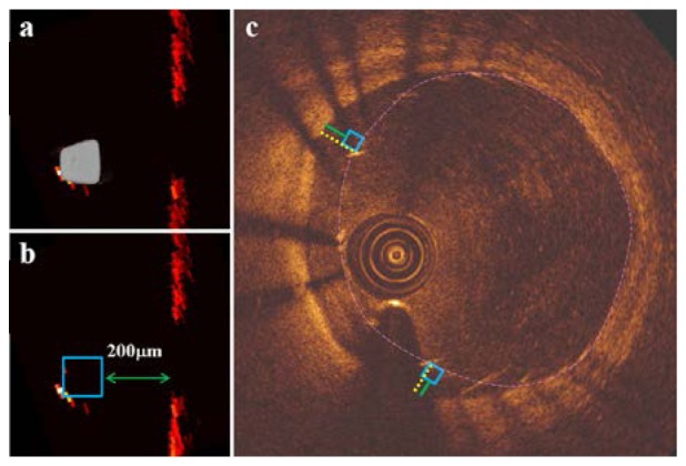
Apparent strut size in a phantom: a) centered catheter, b) eccentric catheter where strut size minimized (both arrows) and sunflowered (large arrow), malapposition measurement: c) approach 1; yellow line is drawn from center of strut blooming to the luminal wall indicating the shortest distance, d) approach 2; box is positioned so that edge is coincident with the leading edge of the stent and green line is drawn perpendicular to the box-edge.

a) Selected strut of a 3 × 8 CYPHER stent deployed in a 3mm diameter phantom vessel, b) cross sectional view of the strut, c) three dimensional STL of the stent strut comprised of 1024 cross sectional images (543microns).

Geometry of IVOCT catheter model and stent strut

Stent strut orientation with respect to IVOCT catheter: a) Catheter positions along the diameter of the vessel perpendicular to the flat side of the strut, rc = −0.50 (P1), 0.00 (P2), 0.50 (P3) and 1.00 mm (P4), b) Catheter positions along a diameter parallel to the flat side of the strut, rc = 0 (P5), 0.30 (P6), 0.60 (P7) and 0.95 mm (P8).

Simulated IVOCT images of a CYPHER stent strut at selected offsets: a)
P1 (rc = −0.5 mm), b)
P2 (rc = 0 mm), c)
P3 (rc = 0.5 mm), d)
P4 (rc = 1 mm).

a) Stent strut orientation with respect to IVOCT catheter at eccentric positions, incident beam (red) and regions on strut reflecting light back into the catheter (yellow) at: b)
P5 (rc = 0 mm), c)
P6 (rc = 0.3 mm), d)
P7 (rc = 0.6 mm), e)
P8 (rc = 0.95 mm).

Apposition measurements of a CYPHER stent strut at selected offsets: a)
P5 (rc = 0 mm) b)
P6 (rc = 0.3 mm) c)
P7 (rc = 0.6 mm) d)
P8 (rc = 0.95 mm), yellow line is drawn from center of strut blooming to the luminal wall indicating the shortest distance (approach 1), box is positioned so that edge is coincident with the leading edge of the stent and green line is drawn perpendicular to the box-edge (approach 2).
a) Actual position of CYPHER stent strut, b) proper box placement provides an accurate malapposition measurement at P8 (rc = 0.95 mm), c) proper box placement based on distribution of all stent struts for accurate malapposition measurement by approach 2, yellow lines represent malapposition measurement by approach 1.
References
-
- S. Mendis, P. Puska, and B. Norrving, “Global Atlas on Cardiovascular Disease Prevention and Control,” WHO, Geneva (2011).
-
- Levine G. N., Bates E. R., Blankenship J. C., Bailey S. R., Bittl J. A., Cercek B., Chambers C. E., Ellis S. G., Guyton R. A., Hollenberg S. M., Khot U. N., Lange R. A., Mauri L., Mehran R., Moussa I. D., Mukherjee D., Nallamothu B. K., Ting H. H., American College of Cardiology FoundationAmerican Heart Association Task Force on Practice GuidelinesSociety for Cardiovascular Angiography and Interventions , “2011 ACCF/AHA/SCAI Guideline for Percutaneous Coronary Intervention. A Report of the American College of Cardiology Foundation/American Heart Association Task Force on Practice Guidelines and the Society for Cardiovascular Angiography and Interventions,” J. Am. Coll. Cardiol. 58(24), e44–e122 (2011).10.1016/j.jacc.2011.08.007 - DOI - PubMed
-
- Brezinski M. E., Tearney G. J., Weissman N. J., Boppart S. A., Bouma B. E., Hee M. R., Weyman A. E., Swanson E. A., Southern J. F., Fujimoto J. G., “Assessing atherosclerotic plaque morphology: comparison of optical coherence tomography and high frequency intravascular ultrasound,” Heart 77(5), 397–403 (1997). - PMC - PubMed
LinkOut - more resources
Full Text Sources
Other Literature Sources