. 2012 Jul;18(4):1313-1325.
doi: 10.1109/JSTQE.2011.2173659.

Polarized Enhanced Backscattering Spectroscopy for Characterization of Biological Tissues at Subdiffusion Length-scales

Affiliations

Polarized Enhanced Backscattering Spectroscopy for Characterization of Biological Tissues at Subdiffusion Length-scales

Andrew J Radosevich et al. IEEE J Sel Top Quantum Electron. 2012 Jul.

Abstract

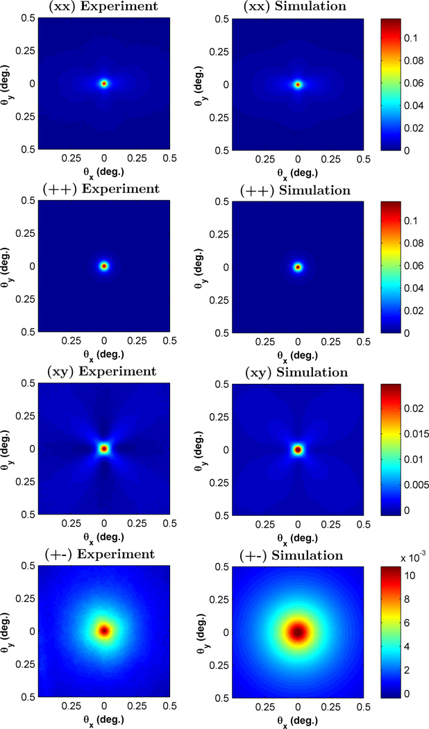
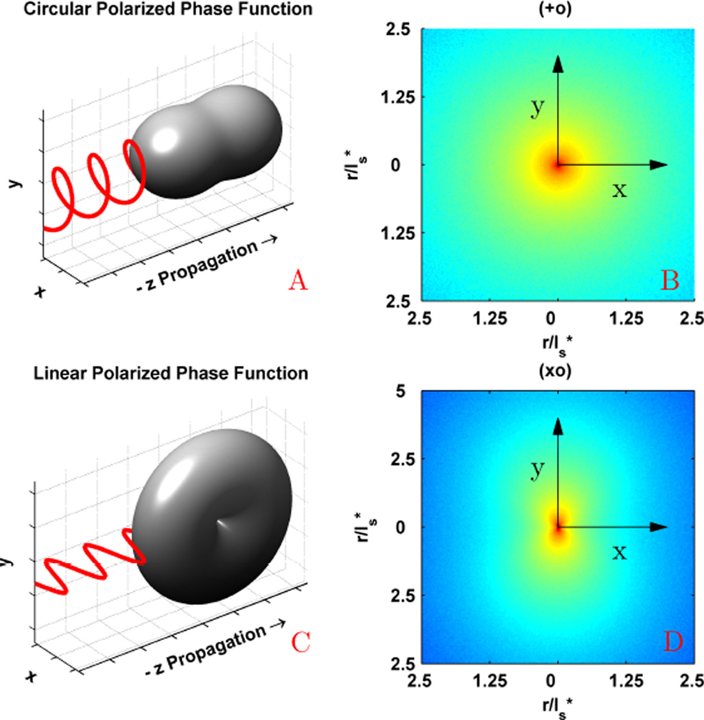
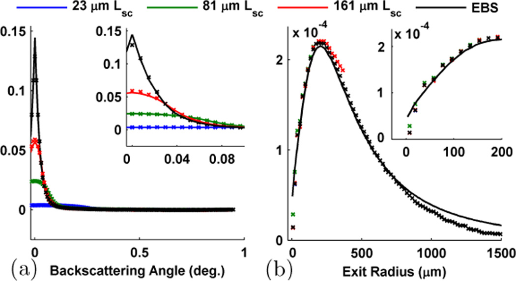
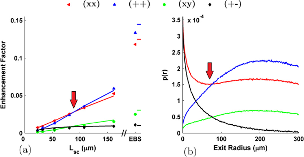
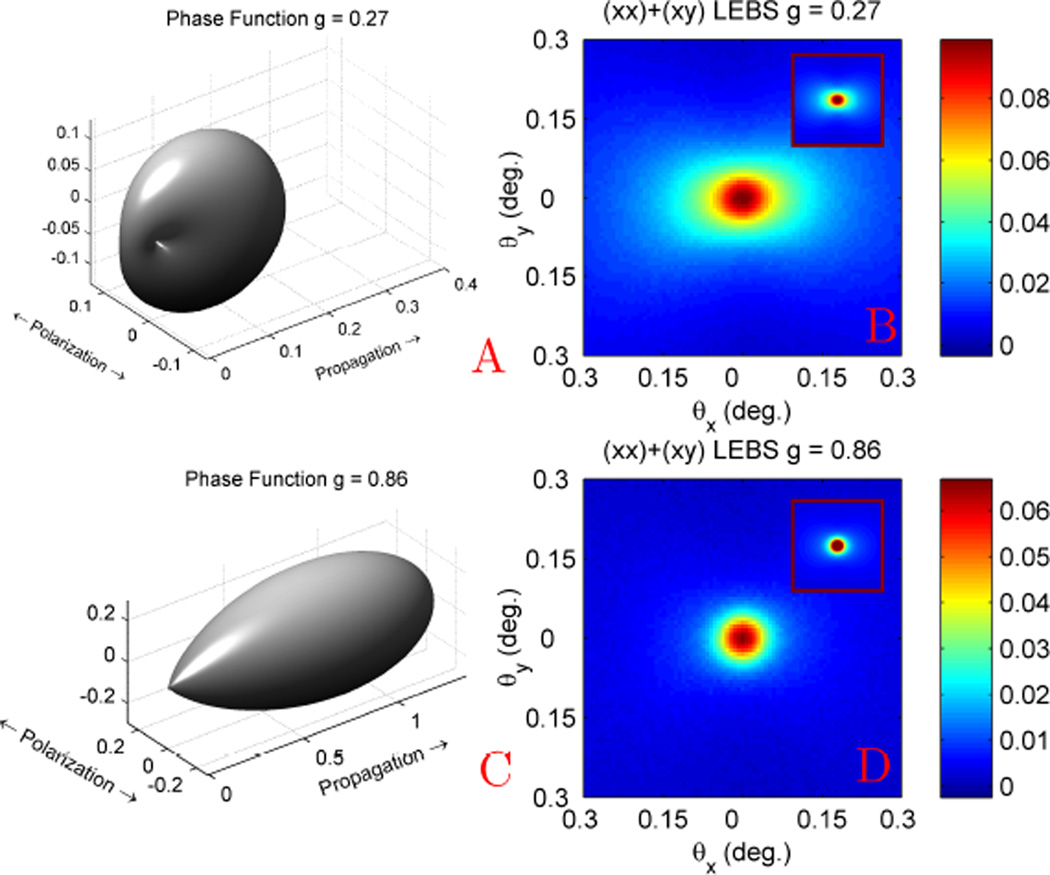
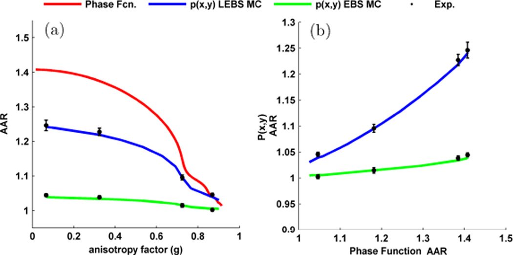
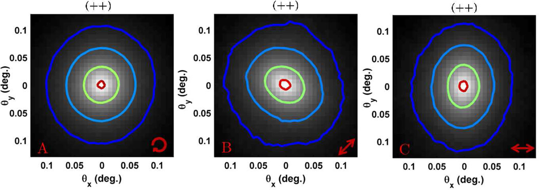
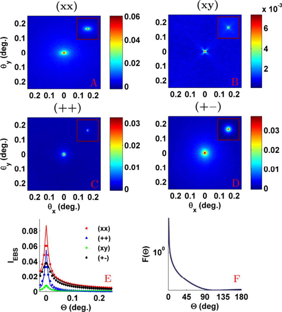
Since the early 1980's, the enhanced backscattering (EBS) phenomenon has been well-studied in a large variety of non-biological materials. Yet, until recently the use of conventional EBS for the characterization of biological tissue has been fairly limited. In this work we detail the unique ability of EBS to provide spectroscopic, polarimetric, and depth-resolved characterization of biological tissue using a simple backscattering instrument. We first explain the experimental and numerical procedures used to accurately measure and model the full azimuthal EBS peak shape in biological tissue. Next we explore the peak shape and height dependencies for different polarization channels and spatial coherence of illumination. We then illustrate the extraordinary sensitivity of EBS to the shape of the scattering phase function using suspensions of latex microspheres. Finally, we apply EBS to biological tissue samples in order to measure optical properties and observe the spatial length-scales at which backscattering is altered in early colon carcinogenesis.

Keywords: Enhanced backscattering; backscattering spectroscopy; cancer detection; polarized light Monte Carlo.


Figures

Fig. 1
Fig. 1
(a) Speckle filled EBS measurement from stationary colon tissue. (b) Speckle reduction obtained with vibration motor placed on sample stage.
Fig. 2
Fig. 2
Example of different Mie and WM phase functions for g = 0.9. (a) The Mie phase function for two different diameter spheres. (b) The WM phase function for different values of D.
Fig. 3
Fig. 3
(a) Monte Carlo simulations to determine the multiple scattering ratio for backscattered light in different polarization channels as function of g. (b) Shows the theoretical EBS enhancement factor for different polarization channels as a function of g.
Fig. 4
Fig. 4
Rotational average of the (++) EBS peak for a microsphere phantom with ls*=205μm and g = 0.87 measured at 633 nm. (a) Peak obtained when normalized by the samples own diffuse baseline. (b) Peak obtained when normalized by the unpolarized incoherent intensity. In each case the theoretical peak must be scaled by 0.65 to obtain a match with experiment.
Fig. 5
Fig. 5
Comparison of the experimental EBS intensity peak with Monte Carlo simulation for the (xx), (++), (xy) and (+−) polarization channels. The sample was a suspension of latex microspheres with g = 0.87 and ls* = 205 µm at 633 nm illumination. The first column shows the experimental peaks while the second column shows the Monte Carlo simulated peaks. Simulation scaled by 0.65 to obtain a match with experiment.
Fig. 6
Fig. 6
Correspondence between the scattering phase function (a,c) and the Monte Carlo Ims(x, y) (b,d) for a medium composed of rayleigh scatterers. (a) Phase function for light with circular polarization in the x-y plane and (b) the resulting Ims(x,y) for the (+o) channel. (c) Phase function for light with linear along the x-axis and (d) the resulting Ims(x,y) for the (xo) channel. For each phase function rendering, the scattering particle is location at the origin.
Fig. 7
Fig. 7
Demonstration of the effect of partial spatial coherence illumination on the EBS peak (i.e. LEBS). (a) Rotational average of the (++) EBS peak for a sample illuminated with different Lsc. (b) p(r) as measured from different Lsc. In each case the solid lines represent Monte Carlo simulations and the symbols represent the experiment. The insets are magnified views showing the distributions at small values of angle and radius. Simulation scaled by 0.65 to obtain a match with experiment.
Fig. 8
Fig. 8
(a) Enhancement factor for the different polarization channels when the microsphere suspension is illuminated with light of different Lsc. Solid lines represent Monte Carlo simulations and the symbols represent the experiment (this includes the EBS values on the right). (b) the corresponding p(r) for each polarization channel in a. Arrows indicate the location of the crossovers discussed in the text. Simulation scaled by 0.65 to obtain a match with experiment.
Fig. 9
Fig. 9
Illustration of the sensitivity of (L)EBS to the shape of the phase function. (a) Linear polarized phase function with g = 0.27 for microspheres with 0.20 µm diameter at 680 nm and (b) LEBS measurement (Lsc = 173 µm). (c) Linear polarized phase function with g = 0.86 for microspheres with 0.65 µm diameter at 680 nm and corresponding LEBS measurement (d). The insets in b and d depict scaled Monte Carlo simulations. Simulation scaled by 0.65 to obtain a match with experiment.
Fig. 10
Fig. 10
Comparison between the AAR for the phase function and p(x, y).(a) AAR for the phase function, p(x, y) measured from LEBS (Lsc = 173µm), and p(x, y) measured from EBS as a function of g. (b) Plot of AAR for EBS and LEBS vs. AAR for the phase function shows a monotonic relationship. LEBS exhibits an increased sensitivity to the shape of the phase function.
Fig. 11
Fig. 11
EBS measurements from the medullary cavity of a chicken thigh bone using (++) polarization. The arrow in the lower right hand side indicates the orientation of the major bone axis. (a) rotating sample (b) bone oriented in the +45° direction (c) bone oriented in the horizontal direction
Fig. 12
Fig. 12
Experimental EBS measurement from a chicken liver sample at 700 nm illumination. (a–d) shows the EBS peaks in the (xx), (xy), (++), and (+−) polarization channels, respectively. (e) Rotational averages of each polarization channel with symbols representing experiment. The WM fit is shown in solid lines for the (xx) and (++) channels. (f) WM phase function for g = 0.95 and D = 2.2. Simulation scaled by 0.65 to obtain a match with experiment.
Fig. 13
Fig. 13
Spectroscopic LEBS analysis to quantify optical absorption. (a) LEBS enhancement spectrum recorded from chicken liver along with the theoretical Hb absorption fit. The arrow indicates the spectrum measured with increasing Lsc. (b) Total Hb α parameter for increasing Lsc.
Fig. 14
Fig. 14
Measurement of p(r) from rectal biopsies using LEBS with Lsc = 166 µm at 650 nm with (xx) polarization. (a) average p(r) measured from rectal biopsy. Compares 11 advanced adenomas (AA) vs. 39 control patients. (b) Difference (AA-control) between p(r)’s shown in panel a.

References

    1. Kuga Y, Ishimaru A. Retroreflectance from a Dense Distribution of Spherical-Particles. J Opt Soc Am A. 1984;vol. 1:831–835.
    1. Tsang L, Ishimaru A. Backscattering Enhancement of Random Discrete Scatterers. J Opt Soc Am A. 1984;vol. 1:836–839.
    1. Wolf PE, Maret G. Weak Localization and Coherent Backscattering of Photons in Disordered Media. Phys Rev Lett. 1985;vol. 55:2696–2699. - PubMed
    1. Van albada MP, Lagendijk A. Observation of Weak Localization of Light in a Random Medium. Phys Rev Lett. 1985;vol. 55:2692–2695. - PubMed
    1. Akkermans E, Wolf PE, Maynard R. Coherent Backscattering of Light by Disordered Media - Analysis of the Peak Line-Shape. Phys Rev Lett. 1986 Apr 7;vol. 56:1471–1474. - PubMed

LinkOut - more resources