. 2013 Nov 8;469(2159):20130351.
doi: 10.1098/rspa.2013.0351.

Folding behaviour of Tachi-Miura polyhedron bellows

Affiliations

Folding behaviour of Tachi-Miura polyhedron bellows

Hiromi Yasuda et al. Proc Math Phys Eng Sci. .

Abstract

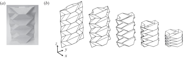
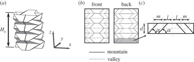
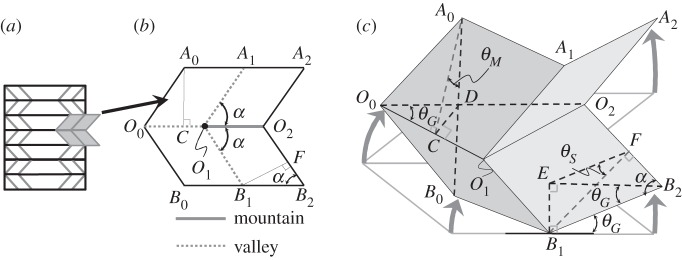
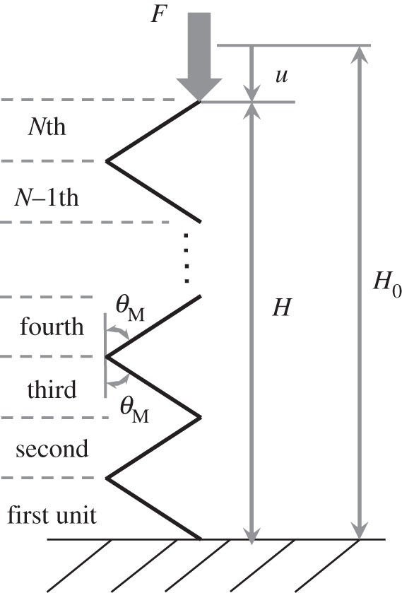
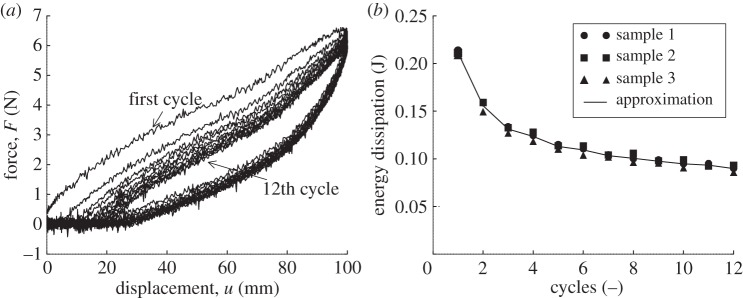
In this paper, we examine the folding behaviour of Tachi-Miura polyhedron (TMP) bellows made of paper, which is known as a rigid-foldable structure, and construct a theoretical model to predict the mechanical energy associated with the compression of TMP bellows, which is compared with the experimentally measured energy, resulting in the gap between the mechanical work by the compression force and the bending energy distributed along all the crease lines. The extended Hamilton's principle is applied to explain the gap which is considered to be energy dissipation in the mechanical behaviour of TMP bellows.

Keywords: Miura-ori; Tachi–Miura polyhedron; energy dissipation; extended Hamilton's principle; origami.


Figures

Figure 1.
Figure 1.
(a) Tachi–Miura polyhedron and (b) its folding motion from left to right.
Figure 2.
Figure 2.
(a) Tachi–Miura polyhedron where the black solid line shown on the side surface is discussed in figure 4, (b) its initial flat sheet geometry and (c) repeating unit cell.
Figure 3.
Figure 3.
(a) Repeating Miura-ori unit cell shown in grey coloured area, (b) its flat sheet, which is folded into (c).
Figure 4.
Figure 4.
Side view of the black line shown in figure 2a.
Figure 5.
Figure 5.
Definition of folding angles of main or sub-crease line θk (k=M,S) at initial (a) and current folding (b).
Figure 6.
Figure 6.
Force–displacement relationship of the TMP bellows under compression.
Figure 7.
Figure 7.
Folding of unit paper cell by accounting for the effect of the paper thickness t.
Figure 8.
Figure 8.
(a) Side view of TMP with θM=0°, showing overlap area (dark shaded area) in which two sheets of paper are attached. Black thick lines indicate the sub-crease lines and dashed lines indicate the main crease lines that are affected by the overlap area, (b) top view of the TMP with θM=90°, showing the number of overlaps in each area. N is the number of repeating unit area.
Figure 9.
Figure 9.
Mθ* relationship of the unit paper cell experiment.
Figure 10.
Figure 10.
Stress–strain curve of a flat sheet under tension.
Figure 11.
Figure 11.
Comparison between experimental data and theoretical prediction of force–displacement relationship of TMP bellows under compression.
Figure 12.
Figure 12.
(a) Initial layout of TMP sheet whose vertices are removed, and (b,c) show the vertices removed.
Figure 13.
Figure 13.
The force–displacement relationship of the TMP bellows under compression where vertices are removed.
Figure 14.
Figure 14.
Change of folding angles θM, θS, θG during compression test of TMP bellows.
Figure 15.
Figure 15.
(a) Definition of the cross-sectional area at height H, (b) Top down view of the TMP. (ai: vertices in coloured xy plane in (a)).
Figure 16.
Figure 16.
Cross section of TMP (ai: vertices at initial state, ai: at final state, black solid lines: path of each vertex) before and after the compression (a) and change of the cross-sectional area as a function of compression displacement (b).
Figure 17.
Figure 17.
(a) Cyclic loading test showing the first to 12th cycle and (b) energy dissipation in each cycle.
Figure 18.
Figure 18.
The crease line of a paper bent; (a) sequence of illustrations and optical micrographs of the initial crease line, and those in the paper under subsequent bending, (b) enlarged view of the crease line by scanning electron micrograph.
Figure 19.
Figure 19.
(a) Completely folded state of unit paper cell and (b) the TMP, (c) view from the arrow shown in (b), focusing on the cross section of the main crease lines (grey thick lines) and the sub-crease lines (black thick lines). The dark shaded area indicates front sheet and white colour is back sheet shown in (b).

References

    1. Guest SD, Pellegrino S. 1994. The folding of triangulated cylinders, part I: geometric considerations. J. Appl. Mech. 61, 773–777 (doi:10.1115/1.2901553) - DOI
    1. Guest SD, Pellegrino S. 1996. The folding of triangulated cylinders, part III: experiments. J. Appl. Mech. 63, 77–83 (doi:10.1115/1.2787212) - DOI
    1. Hunt GW, Ario I. 2005. Twist buckling and the foldable cylinder: an exercise in origami. Int. J. Non-Linear Mech. 40, 833–843 (doi:10.1016/j.ijnonlinmec.2004.08.011) - DOI
    1. Yoshimura Y. 1955. On the mechanism of buckling of a circular cylindrical shell under axial compression, NACA TM 1390.
    1. Ario I, Nakazawa M. 2010. Non-linear dynamic behavior of multi-folding microstructure systems based on origami skill. Int. J. Non-Linear Mech. 45, 337–347 (doi:10.1016/j.ijnonlinmec.2009.11.010) - DOI