. 2013 Dec 3;110(49):E4798-807.
doi: 10.1073/pnas.1310983110. Epub 2013 Nov 18.

Estimating functional connectivity in an electrically coupled interneuron network

Affiliations

Estimating functional connectivity in an electrically coupled interneuron network

Pepe Alcami et al. Proc Natl Acad Sci U S A. .

Abstract

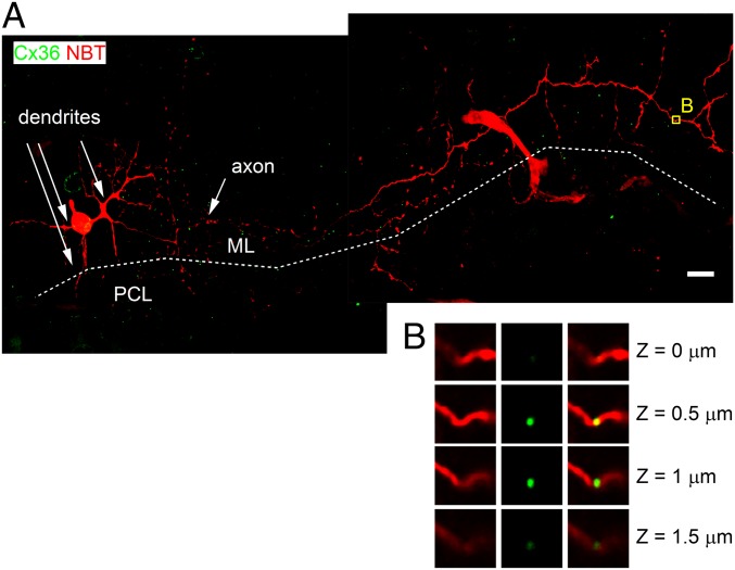
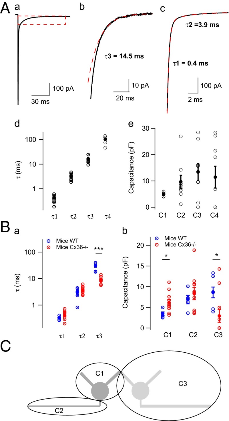
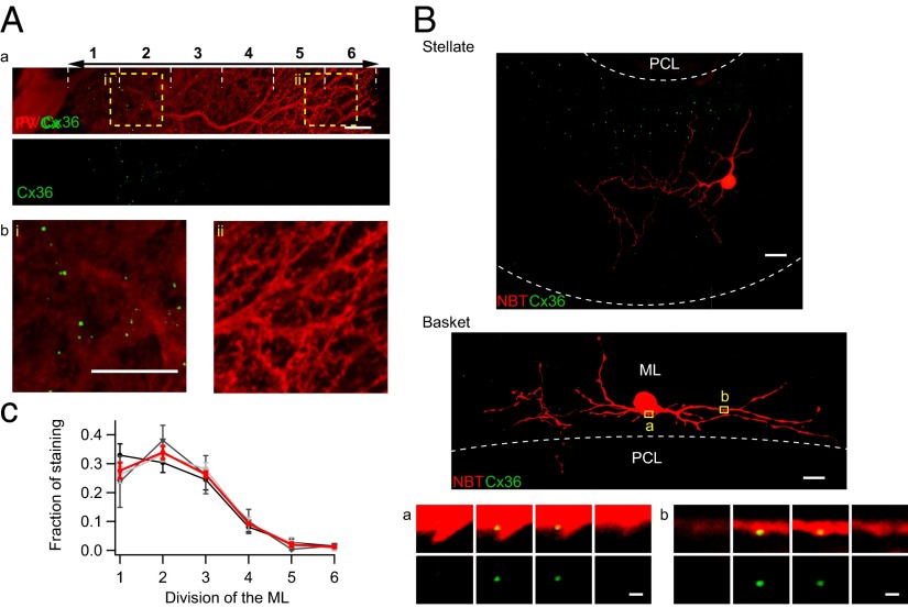
Even though it has been known for some time that in many mammalian brain areas interneurons are electrically coupled, a quantitative description of the network electrical connectivity and its impact on cellular passive properties is still lacking. Approaches used so far to solve this problem are limited because they do not readily distinguish junctions among direct neighbors from indirect junctions involving intermediary, multiply connected cells. In the cerebellar cortex, anatomical and functional evidence indicates electrical coupling between molecular layer interneurons (basket and stellate cells). An analysis of the capacitive currents obtained under voltage clamp in molecular layer interneurons of juvenile rats or mice reveals an exponential component with a time constant of ~20 ms, which represents capacitive loading of neighboring cells through gap junctions. These results, taken together with dual cell recording of electrical synapses, have led us to estimate the number of direct neighbors to be ~4 for rat basket cells and ~1 for rat stellate cells. The weighted number of neighbors (number of neighbors, both direct and indirect, weighted with the percentage of voltage deflection at steady state) was 1.69 in basket cells and 0.23 in stellate cells. The last numbers indicate the spread of potential changes in the network and serve to estimate the contribution of gap junctions to cellular input conductance. In conclusion the present work offers effective tools to analyze the connectivity of electrically connected interneuron networks, and it indicates that in juvenile rodents, electrical communication is stronger among basket cells than among stellate cells.


Conflict of interest statement

The authors declare no conflict of interest.

Figures

Fig. 1.
Fig. 1.
Cx36 mediates electrical coupling between basket cells. (A) Cx36 is expressed at putative contacts between parvalbumin-positive MLIs. Shown is immunostaining for parvalbumin (PV, red), calbindin (CB, blue), and Cx36 (green), in cerebellar slices from juvenile rats. Successive confocal planes are shown. Arrowheads indicate Cx36 puncta, which are associated with PV+, CB cells (presumably MLIs), and are mostly located at crossings between two PV+, CB neurites. (B) Electrical coupling in control and Cx36−/− mice. Shown are whole-cell recordings from pairs of basket cells. Current pulses were injected in cell 1 (black) and the membrane potential was monitored in both the stimulated cell (black) and the other cell (red). Average of ∼50 voltage traces is shown. (a) Representative recordings of pairs of basket cells from wild-type mice, showing steady-state coupling. (b) Representative recording of pairs of basket cells from Cx36−/− mice, showing no electrical connection.
Fig. 2.
Fig. 2.
Axonal location of Cx36 in some MLIs. (A) A basket cell filled with neurobiotin (red) and immunostained against Cx36 (green) displays a compact dendritic arborization and an extended axon running near the edge of the molecular layer (ML), parallel to the Purkinje cell layer (PCL; border between ML and PCL indicated by white line). Maximum of the Z projection from a stack of confocal planes is shown. (B) A magnification of the yellow box in A in four successive confocal planes shows a Cx36 cluster located in the main branch of the basket cell axon.
Fig. 3.
Fig. 3.
Slow component of capacitive currents in basket cells reflects capacitive loading of neighboring cells through the GJ channel connexin 36. (A) Current relaxations evoked by a 50-mV voltage step in rat basket cells. (a) Capacitive current relaxation in a rat basket cell in response to a 50-mV hyperpolarizing jump in voltage-clamp mode (average of ∼100 trials). (b) Enlargement of the red dashed box in a, showing the slow capacitive current (with time constant τ3) present in 8/9 basket cells. In this example, τ3 = 14.5 ms. A monoexponential fit (red) is superimposed to the original average trace (black). (c) The curve resulting from the subtraction of the slow component shown in b from the original data is fitted by a biexponential curve (red), with time constants τ1 = 0.4 ms and τ2 = 3.9 ms. (d) Time constants of the three exponential functions that fit the average current trace: τ1, τ2, and τ3 (n = 8/9) and τ4 (n = 5/9). (e) Capacitance of the corresponding three compartments. (B) Size and charging time constants of successive capacitance current components in mice basket cells. (a) Time constants of the three exponential functions that fit the average current trace in wild-type mice (blue) and in Cx36−/− mice (red). The value of τ3 is significantly smaller in Cx36−/− mice than in control mice. τ1 and τ2 are not significantly different between wild-type mice and Cx36−/− mice. (b) Capacitance of the corresponding three compartments of basket cells in wild-type mice (blue) and Cx36−/− mice (red). Red symbols display means and associated SEM values. The capacitance of the first compartment (C1) is significantly larger in MLIs from Cx36−/− mice than in those from wild-type mice. The capacitance of the second compartment (C2) is not significantly different in Cx36−/− compared with wild-type mice. The capacitance of the third compartment (C3) is significantly reduced in Cx36−/− mice. (C) Diagram of the three capacitive compartments of MLIs. Shown is a schematic representation of the three compartments deduced from current relaxations. C1 and C2 respectively represent the somatodendritic and the axonal compartment of the recorded cell. C3 represents one or several cells linked to the recorded cell by electrical junctions.
Fig. 4.
Fig. 4.
Electrical coupling between MLIs. (A) Steady-state coupling. (a) Diagram of the experiment. Whole-cell recordings from pairs of neurons are shown. Current pulses were injected in one cell while a constant current was applied to the other. (b) (Left) Negative current step injected in cell 1. Average of ∼20 traces is shown. Arrowhead: −70 mV. (Right) Negative current step injected in cell 2. Averages of ∼20 traces are shown. Arrowhead: −70 mV. Cell 1 traces are black and cell 2 traces are red. In both a and b note the sag due to Ih current activation. Steady-state potential was measured at the end of the pulse, after the Ih sag. (c) Histogram of coupling coefficients measured in paired recordings as the ratio between the steady-state voltage change in one cell and the steady-state voltage change in the coupled cell. Note the non-Gaussian distribution, with a mode followed by a tail of large values. (B) Phasic coupling. Strong (2-ms duration) short current injection in one cell elicited a spike in that cell and a postsynaptic potential (spikelet) in the other. (a) (Left) The red trace illustrates average membrane potential of cell 2 triggered by spikes in cell 1 (black). Average of 20 traces is shown. (Right) Averages of the first cell membrane potential (black) triggered by spikes in cell 2 (red). Arrowhead: −70 mV. (b) Histogram of spikelet amplitudes. As in A, note the non-Gaussian distribution, with a mode followed by a tail of large values. (C) Example of a nonconnected pair. (Left) In response to a hyperpolarizing current jump in one cell, no steady-state coupling is observed in the other. (Right) Spikes in one cell fail to evoke spikelets in the other. Arrowhead: −70 mV. (D) Spikelet amplitude as a function of coupling coefficient. Spikelet amplitudes are tightly correlated to corresponding coupling coefficients. Dashed red lines, average values of the two parameters. The data are approximated with a line passing through the axes origin, with a slope of 0.46 mV for 10% coupling coefficient (solid red line).
Fig. 5.
Fig. 5.
Conductance and rectification of electrical synapses between MLIs. (A) Coupling conductance and lack of rectification of electrical coupling in voltage-clamp experiments. (Left) Experimental design and sample traces. Two electrically coupled cells were recorded under voltage clamp (holding potential −62 mV). When cell 1 was hyperpolarized, an inward current was evoked in cell 1 (black). The electrode of cell 2 delivered current (red) to maintain the potential of cell 2 to −62 mV. This current flowed through the GJ from cell 2 to cell 1, and its direction with respect to the amplifier clamping cell 2 was the same as that of depolarizing currents, i.e., outward. Depolarizing cell 1 had the inverse effect. The junctional conductance was then calculated as the ratio of the current change in cell 2 (ΔI2) over the voltage change in cell 1 (ΔV1). (Upper Right) Linear relationship between ΔI2 and ΔV1. A linear fit is superimposed on the experimental data, indicating a lack of voltage dependence of the gap conductance (GGAP = 269 pS). Voltage-clamp errors due to the recording pipette resistance in cell 1 have been corrected. (Lower Right) Junctional conductance normalized to values obtained for ΔV1 excursions between –15 mV and +15 mV. Pooled data for six pairs are shown. Mean ± SD shows no significant rectification. (B) Lack of rectification of electrical coupling in current-clamp experiments. Shown is coupling conductance measurement in electrically coupled pairs from current injections in both directions (from cell 1 to cell 2, G1->2 and from cell 2 to cell 1, G2->1). A line (y = x) is superimposed on the experimental data. (C) Histogram of coupling conductances. Shown is a histogram of junctional conductances (n = 19 pairs) measured in coupled cells. Mean = 190 pS. (D) Spikelet under voltage clamp. In many voltage-clamp recordings, moderate depolarization elicited spikelets that presumably reflected the firing of an electrically coupled neighboring cell following the spread of depolarization through the GJ. Average of 46 traces is shown. (E) Histogram of spikelet amplitudes. Summary data from 33 MLIs are shown. Mean = 13 pA.
Fig. 6.
Fig. 6.
Different levels of Cx36 expression in basket and stellate cells. (A) Gradient of expression of Cx36 in the molecular layer. An antibody targeting the protein parvalbumin (PV) was used to visualize the extent of the molecular layer in young rats (PN 13–14). (Scale bar, 10 μm.) (a) The majority of Cx36 puncta are located in the inner half of the molecular layer, whereas the outer half displays little Cx36 expression. (b) Enlargement of boxes shown in a. (c) Quantification of Cx36 gradient along the molecular layer. Stacks of 5-μm thickness were Z projected (maximum projection). The density of Cx36 puncta was quantified in six divisions of the molecular layer as illustrated in a. Three confocal acquisitions of 143 × 143 μm in different regions of the slice were taken for each of three perfused animals. Means of each animal are in gray or black, and mean among animals is in red. (B) Representative examples of single cells injected with neurobiotin. Maximum Z projection is shown of a stellate cell (Upper) and a basket cell (Lower) from a stack of confocal planes. No Cx36 was detected in the stellate cell shown; two puncta are shown in a basket cell soma and dendrite. (Scale bar, 10 μm.) ML, molecular layer; PCL, Purkinje cell layer. (a and b) Enlarged views from two regions (boxes a and b), showing in a sequence of adjacent horizontal planes (ΔZ = 0.5 μm) a close association of Cx36 staining with basket cell structure. (Scale bar, 1 μm.)
Fig. 7.
Fig. 7.
Model of the electrically coupled basket cell network. (A) Square lattice representation of coupled cells. A central cell (gray) is surrounded by neighbors of the ith order organized in a square lattice. In accord with N1 measurement, the central cell is connected to four first-order neighbors (blue), which are themselves connected to eight second-order neighbors (yellow). Some of the yellow cells are represented by larger circles because they are coupled to two first-order neighbors. (B) Distribution of coupling coefficients of first- and second-order connections. Shown is the distribution of coupling coefficients between basket cells and the theoretical distribution predicted from A (first- and second-order neighbors only). (C) Signal decay in successive coupled layers from a local perturbation in the square lattice. ΔV was computed for each layer of first-, second-, …, fifth-order neighbors in the square lattice, normalized to the value of ΔV in the central cell, for an average cell in each layer (squares) and for the sum of ΔV of all cells belonging to a given layer (circles). (D) Simplified model of the central cell and its electrically coupled neighbors. To model the capacitive current flowing into a first-order neighbor, the input conductance of this cell is approached by a combination of its links to its three other neighbors (through conductance GGAP) plus its intrinsic input conductance 1/RL.

Similar articles

Cited by

References

    1. Galarreta M, Hestrin S. Electrical synapses between GABA-releasing interneurons. Nat Rev Neurosci. 2001;2(6):425–433. - PubMed
    1. Tamás G, Buhl EH, Lörincz A, Somogyi P. Proximally targeted GABAergic synapses and gap junctions synchronize cortical interneurons. Nat Neurosci. 2000;3(4):366–371. - PubMed
    1. Hormuzdi SG, et al. Impaired electrical signaling disrupts gamma frequency oscillations in connexin 36-deficient mice. Neuron. 2001;31(3):487–495. - PubMed
    1. Bartos M, et al. Fast synaptic inhibition promotes synchronized gamma oscillations in hippocampal interneuron networks. Proc Natl Acad Sci USA. 2002;99(20):13222–13227. - PMC - PubMed
    1. Lewis TJ, Rinzel J. Dynamics of spiking neurons connected by both inhibitory and electrical coupling. J Comput Neurosci. 2003;14(3):283–309. - PubMed

Publication types

LinkOut - more resources