. 2014 Apr;12(2):307-23.
doi: 10.1007/s12021-013-9208-z.

From model specification to simulation of biologically constrained networks of spiking neurons

Affiliations

From model specification to simulation of biologically constrained networks of spiking neurons

Paul Richmond et al. Neuroinformatics. 2014 Apr.

Abstract

A declarative extensible markup language (SpineML) for describing the dynamics, network and experiments of large-scale spiking neural network simulations is described which builds upon the NineML standard. It utilises a level of abstraction which targets point neuron representation but addresses the limitations of existing tools by allowing arbitrary dynamics to be expressed. The use of XML promotes model sharing, is human readable and allows collaborative working. The syntax uses a high-level self explanatory format which allows straight forward code generation or translation of a model description to a native simulator format. This paper demonstrates the use of code generation in order to translate, simulate and reproduce the results of a benchmark model across a range of simulators. The flexibility of the SpineML syntax is highlighted by reproducing a pre-existing, biologically constrained model of a neural microcircuit (the striatum). The SpineML code is open source and is available at http://bimpa.group.shef.ac.uk/SpineML .


Figures

Fig. 1
Fig. 1
An incremental addition to the NineML model specification format. The SpineML syntax is a proposed extension to the NineML modelling format which provides a complete syntax for describing models of spiking point neuron models with varying biological complexity. In contrast with libNineML which provides code generation for only the component layer, the completeness of the SpineML syntax allows full simulator support for all three layers of components (neurons, synapses, etc.), networks and experiments
Fig. 2
Fig. 2
The modular dynamics within the three layers of SpineML. The figure shows the modular dynamical structure of the three layers of SpineML specification. A ComponentClass described within the component layer defines the dynamical behaviour of modular functional objects within a simulation (e.g. a neuron, synapse or neuromodulator). The dynamics of a ComponentClass manipulate state variables and emit outputs by evaluating sets of differential equations using only read-only parameters, inputs and aliases (an expression consisting of a mixture of parameters and state variables). The Input and Output ports define an interface allowing a component instance (a component with a unique set of parameters and state variables) to be connected to other instances within the network layer. The figure shows the connectivity of a Neuron and Synapse (Composed of a set of WeightUpdates and a single PostSynapse). The experiment layer defines any additional inputs to the network of connected component instances, e.g. spike sources or current injections
Fig. 3
Fig. 3
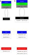
Visual representation of a Leaky Integrate and Fire (LIF) neuron body component. The component transitions between two Regimes (black) according to conditions which test internal state variables of the model. The refractory regime b has no behaviour but persists until the simulation time t exceeds the refractory period tau_refractory. The ‘integrating’ regime a is the initial regime, indicated by the asterisk symbol (*). All Parameters and State Variables referenced within any time derivatives or conditions are shown within the disconnected red box. A single analogue reduce port I_Syn which sums synaptic current inputs and an event output port spike are also shown (in the disconnected blue box) for completeness
Fig. 4
Fig. 4
Diagrammatic representation of a synapse consisting of a fixed-weight update and post-synapse component. The figure shows a fixed-weight update component a which has a single event-based transition causing the emission of an impulse of the synaptic weight. b Shows a exponentially decaying post-synaptic current which decays according to the shown time derivative. On the receipt of an impulse the post-synaptic current (I_Syn) is increased by the impulse value
Fig. 5
Fig. 5
An object model for describing networks of connected components. The figure shows the object model of the SpineML Network Level syntax. Each box represents a high (white) or low (blue) level object corresponding to an XML element within the SpineML description format. The low level format contains only Input and Group allowing the definition of sets of component instances and connections which are able to communicate through mechanisms other than chemical synapses. Relationships between objects are indicated by ownership. i.e. a single a Population contains (or owns) a single Neuron and a single Population contains zero or more Projections. Abstract objects and the Inheritance relationship are shown in grey i.e. a Neuron, WeightUpdate, PostSynapse and Group all inherit AbstractComponentInstance which instantiates a component layer model description. A single SpineML object forms the root of the network layer
Fig. 6
Fig. 6
A tool-chain for simulation through code generation using the SpineML modelling syntax. The SpineML modelling syntax is composed of the Component, Network and Experiment XML description layers, where each is structured according to an XML Schema. Models can be generated manually using XML editors or using graphical user interface (GUI) tools. Translation of a model to any simulator is achieved by using a simulator specific set of XSLT templates to generate simulator code or native simulator model descriptions. Simulator code then logs results in a standardised format which can be used for plotting and analysis
Fig. 7
Fig. 7
Results of running the worked example described using the SpineML format in three different supported simulators. The spike times and membrane potentials of two neurons were logged in NEURON via PyNN, BRAHMS and the DAMSON emulator and subsequently post processed to produce the resulting graphs a through to c which are consistent with results reported in (Davison et al. ; Nordlie et al. 2009) and also with results reported by a model designed natively in PyNN. a Shows the membrane potential for two excitatory neurons. Traces diverge after a short period of time due to differences in numerical integration between simulators which is compounded by the complexity of network activity. b Shows the spike raster plot of excitatory (blue) and inhibitory (green) neurons. c Shows the distribution of pooled inter spike intervals (ISIs) for excitatory (exc) and inhibitory (inh) neurons. d Shows the distribution of the coefficient of variation of the ISI over the populations of neurons
Fig. 8
Fig. 8
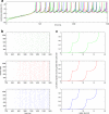
Statistical and Numerical comparison of a Striatal microcircuit model simulated in Native C++ and SpineML via BRAHMS and DAMSON. The Figure shows; a A numerical comparison of the membrane potential of a single Medium Spiny Neuron (MSN) over one and a half seconds of simulation in the C++ model (Green), BRAHMS (Red) and the DAMSON emulator (Blue). b Raster plot of MSN D1 neurons spike times over 700-1400ms of the simulation. Colours as for a. c Cumulative proportion of neurons (y-axis) with an average spike rate greater than the frequency (x-axis) for a simulation (at two input frequencies, F _in=4Hz and 5Hz) over a duration of 10 seconds (discarding the first second as this is when the model is reaching equilibrium). Colours as for a
Fig. 9
Fig. 9
A comparison on the SpineML and PyNN synapse and post-synaptic response models. The Figure shows; a The SpineML synapse encapsulates separate synaptic weight update and post synapse models with a clear separation between the synapse and neuron body model. Typically a neuron will connect to a weight update via event-based communication, weight updates will connect to a post synapse using impulse communication and the post synapse will connect to a projected neuron via analogue communication. There is however no restriction imposing this and any form of event/impulse/analogue communication can occur between models. b PyNN combines the model of post-synaptic response with the model of a post-synaptic neuron. The synapse model (encapsulating only the weight update) is responsible for modelling the synaptic delay, weight and any dynamic behaviour of the synaptic weight. Within PyNN only event-based communication between a neuron (including the post-synaptic model) and a weight update is supported however weight updates may have non event-based internal dynamics i.e. short or long term plasticity

Similar articles

Cited by

References

    1. Brette R, Rudolph M, Carnevale T, Hines M, Beeman D, Bower JM, Diesmann M, Morrison A, Goodman PH, Davison AP, Boustani SE, Destexhe A. Simulation of networks of spiking neurons: a review of tools and strategies. Journal of Computational Neuroscience. 2007;2007:349–398. doi: 10.1007/s10827-007-0038-6. - DOI - PMC - PubMed
    1. Davison, A.P., Brüderle, D., Eppler, J.M., Kremkow, J., Muller, E., Pecevski, D., Perrinet, L., Yger, P. (2009). PyNN: a common interface for neuronal network simulators. Frontiers in Neuroinformatics, 2(11). - PMC - PubMed
    1. Eppler, J.M., Helias, M., Muller, E., Diesmann, M., Gewaltig, M.-O. (2009). PyNEST: a convenient interface to the nest simulator. Frontiers in Neuroinformatics, 2, 12. doi:10.3389/neuro.11.012.2008 - PMC - PubMed
    1. Fox, C.W., Humphries, M.D., Mitchinson, B., Kiss, T., Somogyva, Z., Prescott, T.J. (2009). Technical integration of hippocampus, basal ganglia and physical models for spatial navigation. Frontiers in Neuroinformatics, 3, 6. doi:10.3389/neuro.11.006.2009. - PMC - PubMed
    1. Gansner ER, Koutsofios E, North SC, Vo KP. A technique for drawing directed graphs. IEEE Transactions on Software Engineering. 1993;19(3):214–230. doi: 10.1109/32.221135. - DOI

Publication types