. 2012 Oct;59(5):10.1109/TNS.2012.2207403.
doi: 10.1109/TNS.2012.2207403.

FPGA-Based Pulse Pile-Up Correction With Energy and Timing Recovery

Affiliations

FPGA-Based Pulse Pile-Up Correction With Energy and Timing Recovery

M D Haselman et al. IEEE Trans Nucl Sci. 2012 Oct.

Abstract

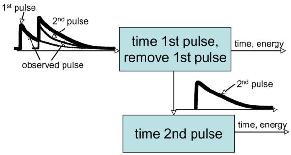
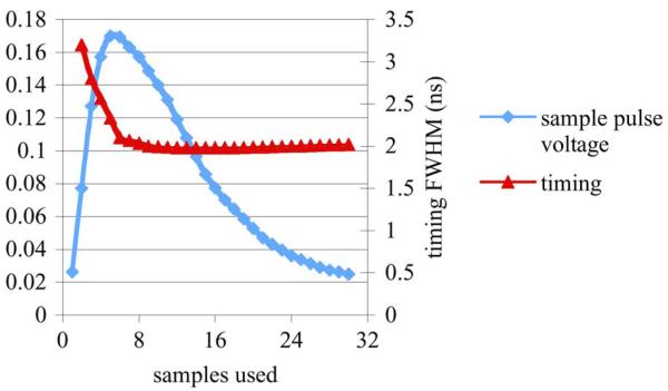
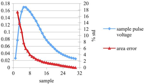
Modern field programmable gate arrays (FPGAs) are capable of performing complex discrete signal processing algorithms with clock rates well above 100 MHz. This, combined with FPGA's low expense, ease of use, and selected dedicated hardware make them an ideal technology for a data acquisition system for a positron emission tomography (PET) scanner. The University of Washington is producing a high-resolution, small-animal PET scanner that utilizes FPGAs as the core of the front-end electronics. For this scanner, functions that are typically performed in dedicated circuits, or offline, are being migrated to the FPGA. This will not only simplify the electronics, but the features of modern FPGAs can be utilized to add significant signal processing power to produce higher quality images. In this paper we report on an all-digital pulse pile-up correction algorithm that has been developed for the FPGA. The pile-up mitigation algorithm will allow the scanner to run at higher count rates without incurring large data losses due to the overlapping of scintillation signals. This correction technique utilizes a reference pulse to extract timing and energy information for most pile-up events. Using pulses acquired from a Zecotech Photonics MAPD-N with an LFS-3 scintillator, we show that good timing and energy information can be achieved in the presence of pile-up utilizing a moderate amount of FPGA resources.

Keywords: Digital signal processing; field programmable gate arrays; imaging; integrated circuits; nuclear medicine; parameter estimation; positron emission tomography; signal analysis; time of arrival estimation.


Figures

Fig. 1
Fig. 1
Block diagram of the overall pulse pile-up correction algorithm.
Fig. 2
Fig. 2
Graph of timing resolution for different amount of pulse used for amplitude normalization for a 65 MHz sampled pulse.
Fig. 3
Fig. 3
Graph of area error as compared to how much of the pulse is interpolated for a 65 MHz sampled pulse.
Fig. 4
Fig. 4
Illustration of how the calculated area of the same pulse can differ based on the voltage of the first sample.
Fig. 5
Fig. 5
Graphs indicating the area summation error based on the voltage of the first sample. (a) For a pulse sampled at 65 MHz while sampling 20% of the pulse or the whole pulse. (b) For a pulse sampled at 65 MHz and 300 MHz summing up 20% of the pulse.
Fig. 6
Fig. 6
Graph of timing resolution versus amount of pulse summed with and without the area corrected for the amplitude of the first sample for a 65 MHz sampled pulse.
Fig. 7
Fig. 7
Graph of area error with and without area correction as compared to how much of the pulse is interpolated for a 65 MHz sampled pulse.
Fig. 8
Fig. 8
Plot of the peak filters ability to detect peak pile-up and percentage of peak pile-up filtered be each part of the filter.
Fig. 9
Fig. 9
Timing resolution for different count rates at different ADC sampling rates.
Fig. 10
Fig. 10
Plot of timing resolution for a 300 MHz ADC sampling for different count rates. The timing resolution is shown for coincidental pulses where neither of the pulse is in a pile-up event, where one of the pulses is piled up and where both of the pulses were in a pile-up event.
Fig. 11
Fig. 11
Graph of the energy resolution of our pulse pile-up correction as count rates increase for different ADC sampling rates.
Fig. 12
Fig. 12
Block diagram of one pulse pile-up correction engine.

References

    1. Lewellen TK, et al. Design of a second generation firewire based data acquisition system for small animal PET scanners; IEEE Nuclear Science Symp. Conf. Record; 2008.pp. 5023–5028. - PMC - PubMed
    1. Lewellen TK, Janes M, Miyaoka RS, Gillespie SB, Park B, Lee KS, Kinahan P. System integration of the MiCES small animal PET scanner; IEEE Nuclear Science Symp. Conf. Record; 2004.pp. 3316–3320.
    1. DeWitt D, Miyaoka RS, Li X, and C. Lockhart,, Lewellen TK. Design of a FPGA based algorithm for real-time solutions of statistics-based positioning; IEEE Nuclear Science Symp. Conf. Record; 2008.pp. 5029–5035. - PMC - PubMed
    1. Haselman MD, Hauck S, Lewellen TK, Miyaoka RS. Simulation of algorithms for pulse timing in FPGAs; IEEE Nuclear Science Symp. Conf. Record; 2007.pp. 3161–3165. - PMC - PubMed
    1. Haselman M, Hauck S, Lewellen TK, Miyaoka RS. FPGA-based pulse parameter discovery for positron emission tomography; IEEE Nuclear Science Symp. Conf. Record; 2009.pp. 2956–2961. - PMC - PubMed

LinkOut - more resources