. 2014 Mar;20(2):10.1109/JSTQE.2013.2279314.
doi: 10.1109/JSTQE.2013.2279314.

Advanced Motion Compensation Methods for Intravital Optical Microscopy

Affiliations

Advanced Motion Compensation Methods for Intravital Optical Microscopy

Claudio Vinegoni et al. IEEE J Sel Top Quantum Electron. 2014 Mar.

Abstract

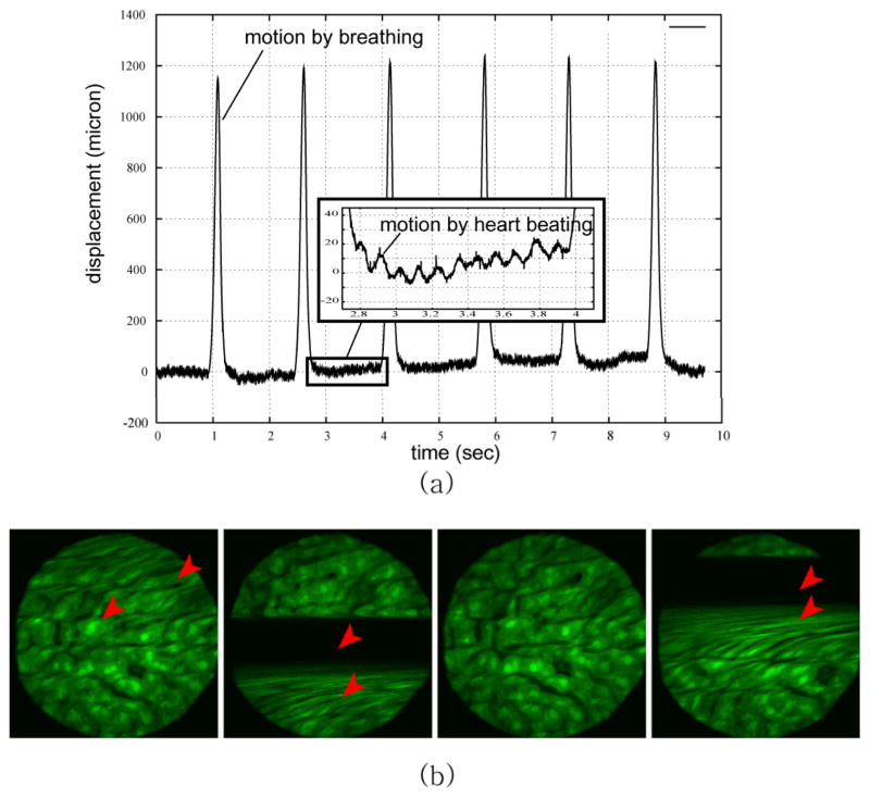
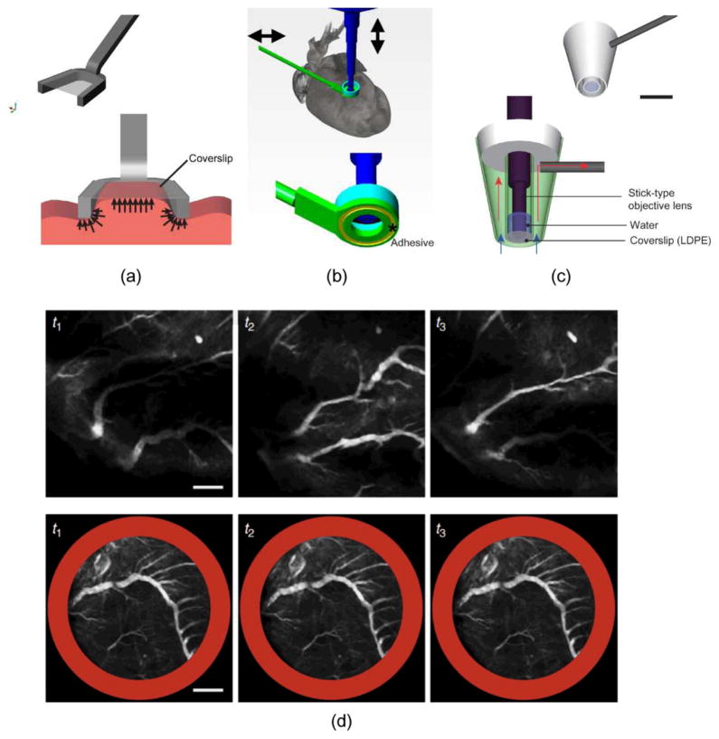
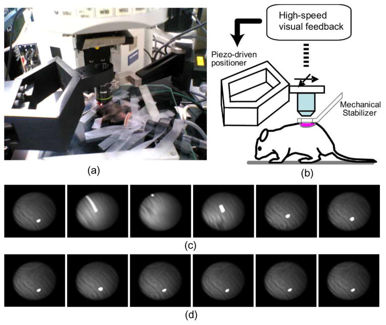
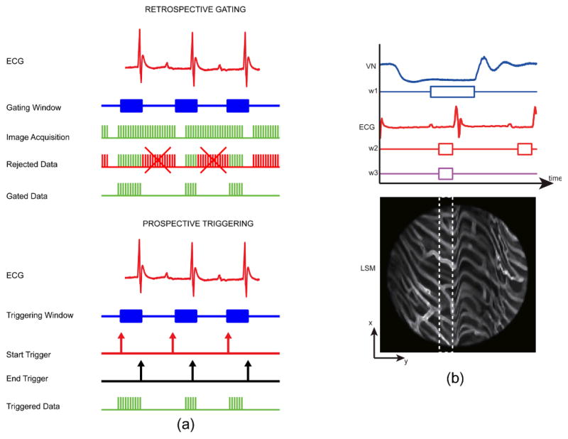
Intravital microscopy has emerged in the recent decade as an indispensible imaging modality for the study of the micro-dynamics of biological processes in live animals. Technical advancements in imaging techniques and hardware components, combined with the development of novel targeted probes and new mice models, have enabled us to address long-standing questions in several biology areas such as oncology, cell biology, immunology and neuroscience. As the instrument resolution has increased, physiological motion activities have become a major obstacle that prevents imaging live animals at resolutions analogue to the ones obtained in vitro. Motion compensation techniques aim at reducing this gap and can effectively increase the in vivo resolution. This paper provides a technical review of some of the latest developments in motion compensation methods, providing organ specific solutions.

Keywords: Intravital microscopy; image stabilization; in vivo imaging; motion artifact and motion compensation.


Figures

Fig. 1
Fig. 1
Motion components during intravital imaging microscopy induce artifacts in the resulting images. (a) Vertical displacements of a mouse liver imaged in vivo, and measured with a laser displacement sensor coaxial with the imaging objective. Separate effects due to both respiratory and cardiac activities are shown. (b) Examples of the resulting motion artifacts in the mouse liver images. Arrows indicates the artifacts. Reprinted with permission from [8]. © 2008 IEEE
Fig. 2
Fig. 2
Examples of various types of mechanical stabilizers (a–c). (a) A compressive mechanical stabilizer for kidney and liver imaging. Reprinted with permission from [13]. © 2012 SPIE. (b) An adhesive based mechanical stabilizer for lung and heart imaging. Reprinted with permission from [10]. © 2012 Nature Publishing Group. (c) A suctioning mechanical stabilizer for lung and heart imaging. Scale bar: 5 mm. Reprinted with permission from [14]. © 2012 Landes Bioscience. (d) Image sequences of the vasculature in a mouse beating heart acquired without (upper row) and with (bottom row) stabilizer. Scale bar: 500 μm. Reprinted with permission from [10]. © 2012 Nature Publishing Group
Fig. 3
Fig. 3
Active motion compensation by high-speed visual feedback control. (a) Stabilized confocal microscopy imaging setup. (b) System configuration: in vivo motion is calculated by a high-speed visual feedback system, and motion is compensated in real-time by moving the objective lens using a piezo-driven robotic closed arm with two degrees of freedom. (c) Unstable image sequence of a mouse kidney. (d) Stabilized image sequence acquired using the high-speed motion compensation system. Reprinted with permission from [8]. © 2008 IEEE
Fig. 4
Fig. 4
(a) Timing diagram of triggering and gating based acquisitions. Retrospective gated acquisition scheme (top): images are continuously acquired while the mouse ECG is simultaneously recorded. Following this non-selective acquisition, only part of the images (patches) that were acquired within the time of a specific gating window are representative of points belonging to the same physical plane. Prospective triggered acquisition scheme (down): images are triggered and acquired only during a specific triggering window which is determined in real time while monitoring cardiac and/or respiratory activity. (b) Double gating of the ECG and the ventilation (VN) signals, and the corresponding minimum artifact area (white dashed line box) within the raw acquired image. The ventilation gating window, w1 is chosen at the time of the end phase of expiration while the ECG gating window w2 is chosen at the time of the end diastole. Both gating windows thus correspond to the time of minimum motion for both lungs and heart, respectively. Reprinted with permission from [14]. © 2012 Landes Bioscience.
Fig. 5
Fig. 5
(a) Scheme of principle for laser scanning confocal microscopy. Two galvanometer mirrors oscillating on orthogonal axes scan the excitation laser beam along a raster path. Light is focused onto the sample and the emission light is descanned and detected through a dichroic mirror. (b) The raster scanning path lies on a horizontal imaging plane (top) perpendicular to the imaging objective. When the subject moves, the imaging plane in the organ’s reference frame will appear as a curved surface (bottom) modulated in time according to the motion periodicity. Reprinted with permission from [13]. © 2012 SPIE.
Fig. 6
Fig. 6
Scheme of retrospective breathing-gated image reconstruction. (a) Having the knowledge of the motion function z(t), here modeled for simplicity as a sinusoidal function, it is possible to set a specific time gating window TGW triggered on a particular phase of the motion. (b) By collecting several images (I1, I2, I3, …), and selecting the corresponding “patches” we can reconstruct an image where each point has the same height within in the imaged volume. (c) A reconstructed motion-free image obtained starting from raw images, using the retrospective breathing-gated image reconstruction technique. Reprinted with permission from [13]. © 2012 SPIE.
Fig. 7
Fig. 7
Examples of motion compensated microscopy for in vivo mouse imaging. Planar (a) and tomographic (b) reconstruction of a mouse kidney imaged in vivo [13]. Planar (c) and tomographic reconstructions (d) of the in vivo beating heart [10]. Scale bars: 50 μm. Reprinted with permission from [10]. © 2012 Nature Publishing Group. Reprinted with permission from [13]. © 2012 SPIE.

References

    1. Weigert R, Sramkova M, Parente L, Amornphimoltham P, Masedunskas A. Intravital microscopy: a novel tool to study cell biology in living animals. Histochem Cell Biol. 2010 May;133:481–91. - PMC - PubMed
    1. Pittet MJ, Weissleder R. Intravital imaging. Cell. 2011 Nov 23;147:983–91. - PMC - PubMed
    1. Bousso P, Moreau HD. Functional immunoimaging: the revolution continues. Nat Rev Immunol. 2012 Dec;12:858–64. - PubMed
    1. Ritsma L, Ponsioen B, van Rheenen J. Intravital imaging of cell signaling in mice. IntraVital. 2012;1:0–8.
    1. Mai W, Badea CT, Wheeler CT, Hedlund LW, Johnson GA. Effects of breathing and cardiac motion on spatial resolution in the microscopic imaging of rodents. Magn Reson Med. 2005 Apr;53:858–65. - PubMed

LinkOut - more resources