Review
. 2013 Oct 29;7(5):51502.
doi: 10.1063/1.4826935. eCollection 2013.

Microfluidic devices for cell cultivation and proliferation

Affiliations
Review

Microfluidic devices for cell cultivation and proliferation

Masoomeh Tehranirokh et al. Biomicrofluidics. .

Abstract

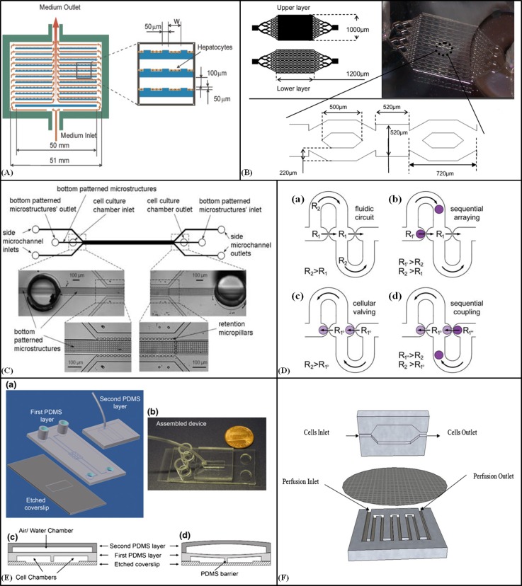
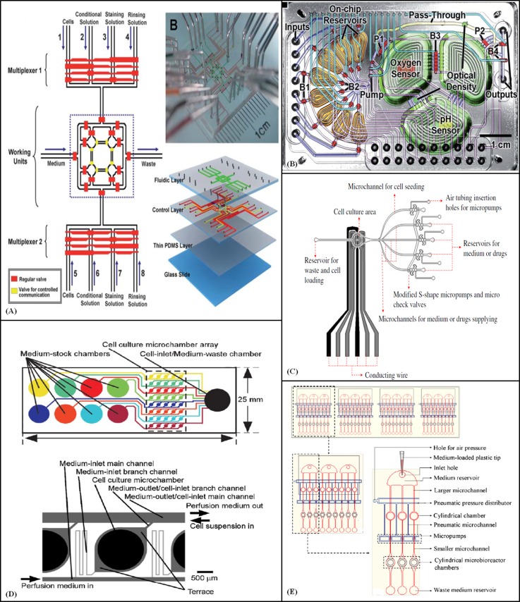
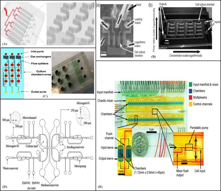
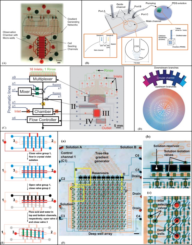
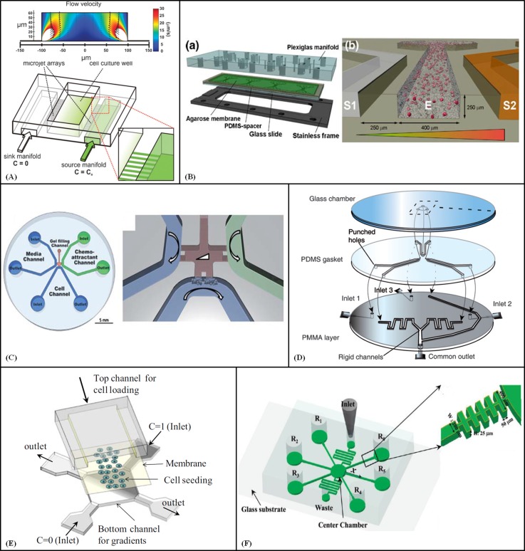
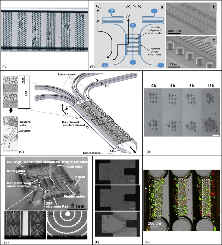
Microfluidic technology provides precise, controlled-environment, cost-effective, compact, integrated, and high-throughput microsystems that are promising substitutes for conventional biological laboratory methods. In recent years, microfluidic cell culture devices have been used for applications such as tissue engineering, diagnostics, drug screening, immunology, cancer studies, stem cell proliferation and differentiation, and neurite guidance. Microfluidic technology allows dynamic cell culture in microperfusion systems to deliver continuous nutrient supplies for long term cell culture. It offers many opportunities to mimic the cell-cell and cell-extracellular matrix interactions of tissues by creating gradient concentrations of biochemical signals such as growth factors, chemokines, and hormones. Other applications of cell cultivation in microfluidic systems include high resolution cell patterning on a modified substrate with adhesive patterns and the reconstruction of complicated tissue architectures. In this review, recent advances in microfluidic platforms for cell culturing and proliferation, for both simple monolayer (2D) cell seeding processes and 3D configurations as accurate models of in vivo conditions, are examined.


Figures

Figure 1
Figure 1
2D and 3D cell culture. (A) Schematic diagram of the radial-flow bioreactor with microgrooves for 2D culture of Hepatocytes. Reprinted with permission from Park et al., Biotechnol. Bioeng. 99, 455–467 (2008). Copyright 2007 Wiley Periodicals, Inc., John Wiley and Sons. (B) Design of the microfluidic bioreactor for hepatocarcinoma cultivation in 3D cell layers. Reprinted with permission from Baudoin et al., Biochem. Eng. J. 53, 172–181 (2011). Copyright 2011 Elsevier. (C) Schematic diagram of perfusion-based microfluidic device with a series of retention micropillars for 3D culture. Reproduced by permission from Goral et al., Lab Chip 10, 3380–3386 (2010). Copyright 2010 by The Royal Society of Chemistry. (D) The cellular valving principle for cell pairing. (a) A spherical channel with a series of apertures. (b) Cell trapping. (c) Diverting the streamline. (d) Flow reversal used to introduce a second spherical cell type and sequential single cell pairing. Reproduced by permission from Frimat et al., Lab Chip 11, 231–237 (2011). Copyright 2011 by The Royal Society of Chemistry. (E) (a) A schematic of the microfluidic cell co-culture platforms to study cell-cell interactions for 2D and 3D culture. (b) The fabricated device. (c) and (d) Diagrams of the barrier valve working mechanism. Reprinted with permission from Gao et al., Biomed. Microdevices 13(3), 539–548 (2011). Copyright 2011 Springer Science+Business Media. (F) Schematic of the microfluidic 2D cell culture device with a sandwiched PC membrane between culture chamber and perfusion chamber. Reprinted with permission Shah et al., Sens. Actuators, B 156, 1002–1008 (2011). Copyright 2011 Elsevier.
Figure 2
Figure 2
Integration and multiplexing. (A) Four layer integrated microfluidic system for studying cell-microenvironmental interactions with four culture chambers. Reproduced by permission from Liu et al., Lab Chip 10, 1717–1724 (2010). Copyright 2010 by The Royal Society of Chemistry. (B) An automated and continuous cell culture device. Reproduced by permission from Lee et al., Lab Chip 11, 1730–1739 (2011). Copyright 2011 by The Royal Society of Chemistry. (C) Illustration of a platform comprising modules for cell culture and temperature control. Reprinted with permission from Hsieh et al., Biomed. Microdevices 11(4), 903–913 (2009). Copyright 2009 Springer Science+Business Media (Figure 1(a)). (D) Microchamber array and microchannel networks of the perfusion culture chip. Reprinted with permission from Sugiura et al., Biotechnol. Bioeng. 100, 1156–1165 (2008). Copyright 2008 Wiley Periodicals, Inc., John Wiley and Sons. (E) Top view layout of the microfluidic cell culture chip, the close-up view of each section, and each cell culture unit. Reprinted with permission from Wu et al., Sens. Actuators, B 155(1), 397–407 (2010). Copyright 2010 Elsevier.
Figure 3
Figure 3
Cell culture for stem cell research. (A) Illustration of a microfluidic device with microtraps for the formation of embryonic bodies. Reprinted with permission from Khoury et al., Biomed. Microdevices 12, 1001–1008 (2010). Copyright 2010 Springer Science+Business Media (Figure 1). (B) Photograph of (a) 1 × 4 and (b) 4 × 4 cell culture arrays with logarithmic flow rates for perfusion. Reproduced by permission from Kim et al., Lab Chip 6, 394–406 (2006). Copyright 2006 by The Royal Society of Chemistry. (C) Micro-bioreactor array for controlling cellular environments with four equal parts. Reprinted with permission from Cimetta et al., Methods 47, 81–89 (2009). Copyright 2009 Elsevier. (D) Schematic representation of the automatic microfluidic system for the culture and differentiation of stem cells with four identical modules. Reprinted with permission from Wu et al., Biomed. Microdevices 11, 869–881 (2009). Copyright 2009 Springer Science+Business Media (Figure 1). (E) An automated cell culture chip. Reprinted with permission from Gómez-Sjöberg et al., Anal. Chem. 79, 8557–8563 (2007). Copyright 2007 American Chemical Society.
Figure 4
Figure 4
Gradient-generating devices based on streams of laminar flow. (A) A device composed of two microfabricated PDMS layers containing gradient generating network, cell seeding channels, observation chamber and control valves. Reproduced by permission from Wang et al., Lab Chip 8, 227–237 (2008). Copyright 2008 by The Royal Society of Chemistry. (B) Schematic of chemical and mechanical gradients generator device with a circular main channel. Reproduced by permission from Park et al., Lab Chip 9, 2194–2202 (2009). Copyright 2009 by The Royal Society of Chemistry. (C) Multipurpose and computer-controlled microfluidic perfusion device. Reproduced by permission from Cooksey et al., Lab Chip 9, 417–426 (2009). Copyright 2009 by The Royal Society of Chemistry. (D) Fluid distribution with the branch channels and the circular channels of the 2-inlet radial gradient generator. Reproduced by permission from Yang et al., Lab Chip 11, 3305–3312 (2011). Copyright 2011 by the Royal Society of Chemistry. (E) Operation of the microchip to generate stepwise gradient. Valve channels groups are shown (red = closed and pink = open). The fluidic channels are in the shape of a ladder (blue, grey, and black colours stand for different solutions). Reprinted with permission from Dai et al., Biomicrofluidics 4, 1–14 (2010). Copyright 2010 American Institute of Physics. (F) (a) 2D microfluidic combinatorial dilution device with a tree-like gradient generator (TLGG) and a microfluidic active injection system that mixes two input solutions and pre-filled solutions in wells to fill array of deep wells with different relative concentrations. (b) and (c) Enlarged view of reservoirs and deep wells. Reproduced by permission from Jang et al., Lab Chip 11, 3277–3286 (2011). Copyright 2011 by The Royal Society of Chemistry.
Figure 5
Figure 5
Gradient-generating devices based on diffusion from a concentrated source. (A) Schematic of the device with a central open-surface reservoir (and its fluid dynamic simulation), two microchannels as sink and source and two arrays of microchannels. Reproduced by permission from Bhattacharjee et al., Integr. Biol. 2, 669–679 (2010). Copyright 2010 by The Royal Society of Chemistry. (B) Agarose based microfluidic device with four three-channel units. Reprinted with permission from Haessler et al., Biomed. Microdevices 11, 827–835 (2009). Copyright 2009 Springer Science+Business Media (Figure 1). (C) Three-channel microfluidic device developed to study neurite turning in 3D scaffolds under growth factor gradients. Reproduced by permission from Kothapalli et al., Lab Chip 11, 497–507 (2011). Copyright 2011 by The Royal Society of Chemistry. (D) A microfluidic device capable of generating multiple spatial chemical gradients with balanced input flow rates. Reproduced by permission from Atencia et al., Lab Chip 9, 2707–2714 (2009). Copyright 2009 by The Royal Society of Chemistry. (E) Schematic of the gradient generator device with a membrane separating the cell loading and gradient sections. Reprinted with permission from Kim et al., Biomed. Microdevices 11, 65–73 (2009). Copyright 2009 Springer Science+Business Media (Figure 1). (F) Schematic of the long-range concentration gradient generator with H-shaped channel structure. Reprinted with permission from M. Kim and T. Kim, Anal. Chem. 82, 9401–9409 (2010). Copyright 2010 American Chemical Society.
Figure 6
Figure 6
(A) MCF-7 cells captured and cultured (for 4 h) on the patterned beads inside a microfluidic channel. Reprinted with permission from Sivagnanam et al., Langmuir 26, 6091–6096 (2010). Copyright 2010 American Chemical Society. (B) (a) Microfluidic device for single neuron arraying, with culture chambers interconnected by neurite outgrowth channels for neuron trapping. (b) and (c) SEM images of the array and Trident-shaped neuron trapping structures. Reproduced by permission from Dinh et al., Lab Chip 13, 1402–1412 (2013). Copyright 2013 by The Royal Society of Chemistry. (C) The layered structure of the 3D neural cell culture. The hydrogel or cell loaded hydrogel flow in through the four inlet channels, through the main channel and exit the outlet channel. Reprinted with permission from Kunze et al., Biomaterials 32, 2088–2098 (2011). Copyright 2011 Elsevier. (D) Cell growth and stagnation during 18 hr by loading into a 3 × 3 drain structure. Reproduced by permission from Zeitoun et al., Lab Chip 10, 1142–1147 (2010). Copyright 2010 by The Royal Society of Chemistry. (E) The cell-patterning chip, the SEM image of the electrode geometry and the close-view of the concentric ring electrodes with stellate-tips. Reproduced by permission from Ho et al., Lab Chip 6, 724–734 (2006). Copyright 2006 by The Royal Society of Chemistry. (F) Optical micrographs of cardiac myocytes orientation in the microfluidic device. Reprinted with permission from M. Yang and X. Zhang, Sens. Actuators, A 135, 73–79 (2007). Copyright 2007 Elsevier. (G) Adherent cells after 10 min perfusion with medium. Direction of flow is indicated by arrow. The shape of the gap surface is outlined by dashed lines. Reprinted with permission from Schütte et al., Biomed. Microdevices 13(3), 493–501 (2011). Copyright 2011 Springer Science+Business Media (Figure 10(d)).

References

    1. El-Ali J., Sorger P. K., and Jensen K. F., “ Cells on chips,” Nature 442, 403–411 (2006).10.1038/nature05063 - DOI - PubMed
    1. Whitesides G. M., “ The origins and the future of microfluidics,” Nature 442, 368–373 (2006).10.1038/nature05058 - DOI - PubMed
    1. Feng X., Du W., Luo Q., and Liu B. F., “ Microfluidic chip: Next-generation platform for systems biology,” Anal. Chim. Acta 650, 83–97 (2009).10.1016/j.aca.2009.04.051 - DOI - PubMed
    1. Squires T. M. and Quake S. R., “ Microfluidics: Fluid physics at the nanoliter scale,” Rev. Mod. Phys. 77, 977–1026, 2005.10.1103/RevModPhys.77.977 - DOI
    1. Ho C. M. and Tai Y. C., “ Micro-electro-mechanical-systems (MEMS) and fluid flows,” Annu. Rev. Fluid Mech. 30, 579–612 (1998).10.1146/annurev.fluid.30.1.579 - DOI