. 2015 Aug;17(4):681-92.
doi: 10.1111/cid.12167. Epub 2013 Nov 28.

Surface Damage on Dental Implants with Release of Loose Particles after Insertion into Bone

Affiliations

Surface Damage on Dental Implants with Release of Loose Particles after Insertion into Bone

Plinio Senna et al. Clin Implant Dent Relat Res. 2015 Aug.

Abstract

Background: Modern dental implants present surface features of distinct dimensions that can be damaged during the insertion procedure into bone.

Purpose: The aims of this study were (1) to quantify by means of roughness parameters the surface damage caused by the insertion procedure of dental implants and (2) to investigate the presence of loose particles at the interface.

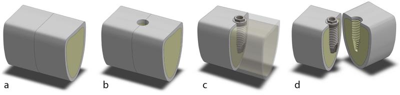
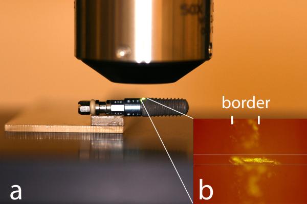
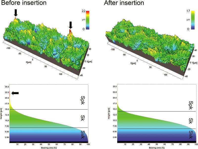
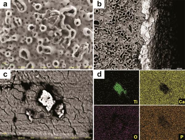
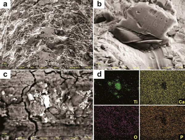
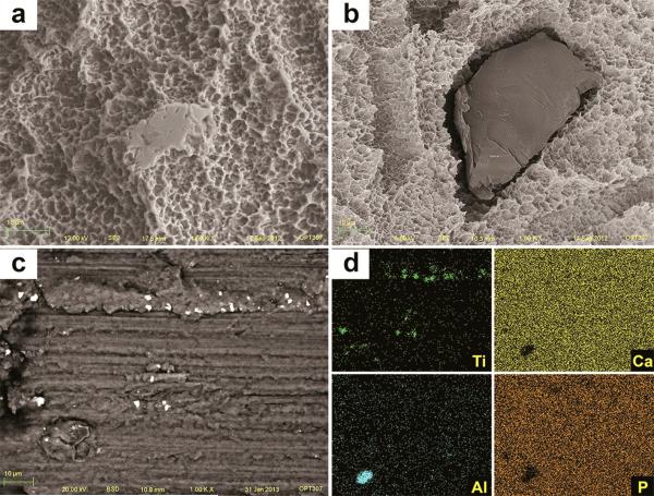
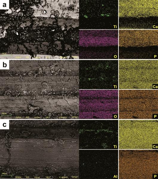
Materials and methods: Three groups of dental implants representing different surface topographies were inserted in fresh cow rib bone blocks. The surface roughness was characterized by interferometry on the same area before and after the insertion. Scanning electron microscopy (SEM)-back-scattered electron detector (BSD) analysis was used to identify loose particles at the interface.

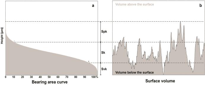
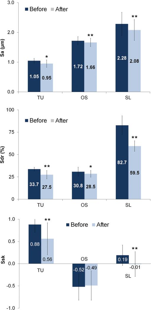
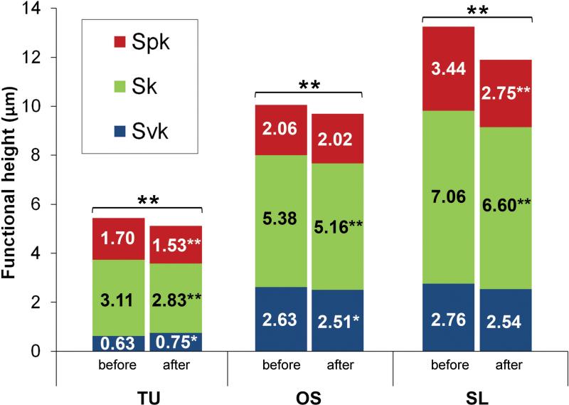
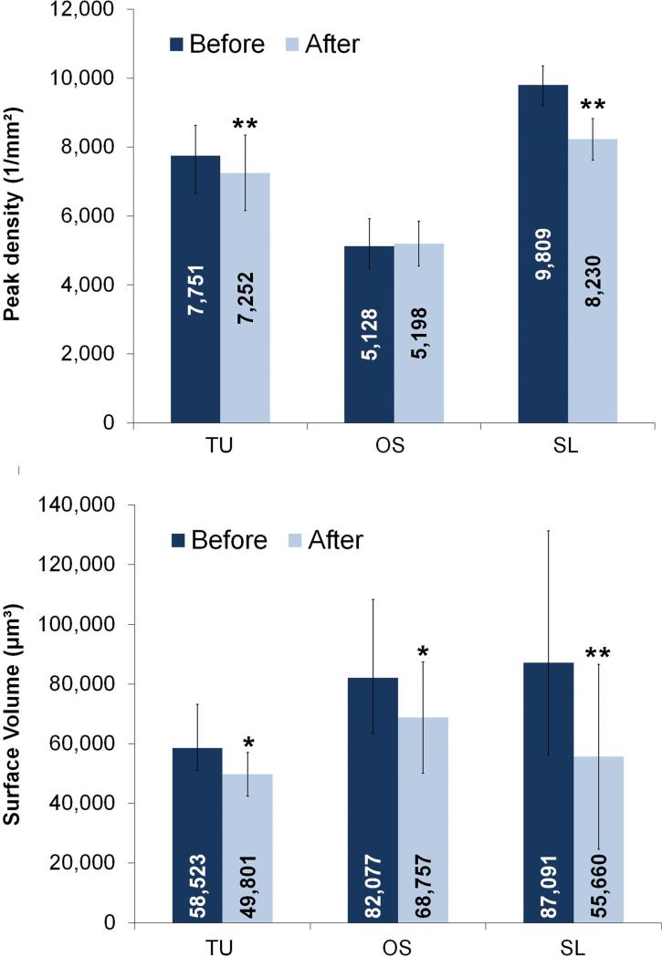
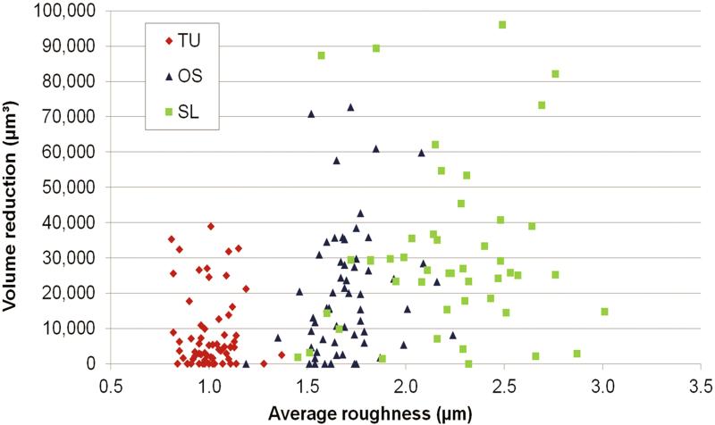
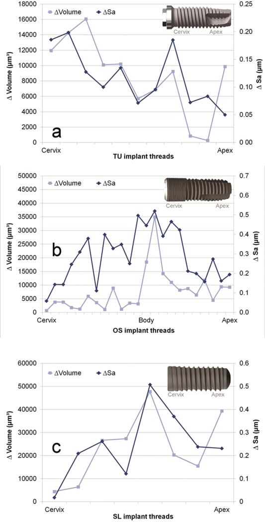
Results: The amplitude and hybrid roughness parameters of all three groups were lower after insertion. The surface presenting predominance of peaks (Ssk [skewness] > 0) associated to higher structures (height parameters) presented higher damage associated to more pronounced reduction of material volume. SEM-BSD images revealed loose titanium and aluminum particles at the interface mainly at the crestal cortical bone level.

Conclusions: Shearing forces during the insertion procedure alters the surface of dental implants. Loose metal particles can be generated at bone-implant interface especially around surfaces composed mainly by peaks and with increased height parameters.

Keywords: bone; dental implants; surface properties; surface topography; titanium.


Figures

Figure 1
Figure 1
Cow rib bone blocks – 20 × 15 × 15 mm were cut transversely (a) and drilling was performed at the interface, as recommended for dense bone (b). After the implants were fully inserted (c), the blocks were split and the implant was assessed without any additional damage to the implant surface (d).
Figure 2
Figure 2
Implant positioning was obtained using the mount fixed to a slide (a). In addition, a scratch mark ensured the exact alignment to a predetermined mask set on the live display window of the software (b).
Figure 3
Figure 3
The functional parameters are determined from the bearing area ratio curve (a). Spk corresponds to the peak height above the core roughness; Sk to the core roughness height (peak-to-valley) of the surface with the predominant peaks and valleys removed; and Svk to valley depth below the core roughness. The sum of these parameters (Svk + Sk + Spk) determines the total structural height of the surface and the volume of surface features (Vm) comprises 100% of the surface material ratio (b).
Figure 4
Figure 4
Surface roughness Sa, Sdr and Ssk parameters (mean and standard deviation) of the implants before and after insertion into bone (* = P < 0.05 and ** = P < 0.01).
Figure 5
Figure 5
The surface functional height (Svk+Sk+Spk) of implants before (B) and after (A) insertion into bone (* = P < 0.05 and ** = P < 0.01).
Figure 6
Figure 6
The surface topography of a thread of SL implants before and after insertion into bone and respective bearing area curves. Summits (red peaks) were visually less prevalent after implant insertion.
Figure 7
Figure 7
Peak density and surface volume (mean and standard deviation) of implants before and after insertion into bone (* = P < 0.05 and ** = P < 0.01).
Figure 8
Figure 8
The surface volume reduction after implant insertion according to the average roughness (Sa) computed at the crest of all threads of TU, OS and SL groups.
Figure 9
Figure 9
The average roughness (Sa) and surface volume (Vm) reduction on each individual thread after insertion along TU (a), OS (b) and SL (c) implants.
Figure 10
Figure 10
SEM image of TU implant after insertion into bone revealed chipping of the more extreme porous (a) and cracks on the oxide layer associated to loss of entire oxide layer at the cutting edge with exposure of the bulk Ti (b). Along the implantation sites, pieces of the oxide layer were identified by SEM-BSD (c) and their Ti content was shown by EDS mapping of the surface (d).
Figure 11
Figure 11
SEM image of OS implant after insertion into bone revealed sharp peaks less prominent or completely removed, resulting in flattened smooth areas after implant insertion (a). Also, the TiO2 grit-particles (dark and smooth) embedded into the surface (b) were less prevalent after insertion. Along the implantation sites, particles were identified by SEM-BSD (c) and their Ti content was shown by EDS mapping of the surface (d).
Figure 12
Figure 12
SEM image of SL implant after insertion into bone revealed sharp peaks less prominent or completely removed, resulting in flattened smooth areas after implant insertion (a). Also, the alumina grit-particles (dark and smooth) embedded into the surface (b) were less prevalent after insertion. Along the implantation sites, particles were identified by SEM-BSD (c) and their Ti and Al content was shown by EDS mapping of the surface (d).
Figure 13
Figure 13
SEM-BSD images of the implantation sites showed titanium loose particles (white shiny spots) along all implantation sites after removal of TU (a), OS (b) and SL implants (c). The elemental content of those particles (Ti for TU and OS, and Ti and Al for SL implants) was confirmed by the EDS mapping of the surface.

References

    1. Albrektsson T, Zarb G, Worthington P, Eriksson AR. The long-term efficacy of currently used dental implants: a review and proposed criteria of success. Int J Oral Maxillofac Implants. 1986;1:11–25. - PubMed
    1. Branemark PI, Hansson BO, Adell R, Breine U, Lindstrom J, Hallen O, Ohman A. Osseointegrated implants in the treatment of the edentulous jaw. Experience from a 10-year period. Scand J Plast Reconstr Surg Suppl. 1977;16:1–132. - PubMed
    1. Collaert B, Wijnen L, De Bruyn H. A 2-year prospective study on immediate loading with fluoride-modified implants in the edentulous mandible. Clin Oral Implants Res. 2011;22:1111–1116. - PubMed
    1. Dong WP, Stout KJ. An Integrated Approach to the Characterization of Surface Wear .1. Qualitative Characterization. Wear. 1995;181:700–716.
    1. Flatebo RS, Hol PJ, Leknes KN, Kosler J, Lie SA, Gjerdet NR. Mapping of titanium particles in peri-implant oral mucosa by laser ablation inductively coupled plasma mass spectrometry and high-resolution optical darkfield microscopy. J Oral Pathol Med. 2011;40:412–420. - PubMed

Publication types

Substances

LinkOut - more resources