. 2012 Jun 15:(Suppl 8):007.
doi: 10.4172/2155-9880.s8-007.

Congenital Heart Defects in Adults : A Field Guide for Cardiologists

Affiliations

Congenital Heart Defects in Adults : A Field Guide for Cardiologists

Anitra Romfh et al. J Clin Exp Cardiolog. .

Abstract

Advances in cardiology and cardiac surgery allow a large proportion of patients with congenital heart defects to survive into adulthood. These patients frequently develop complications characteristic of the defect or its treatment. Consequently, adult cardiologists participating in the care of these patients need a working knowledge of the more common defects. Occasionally, patients with congenital heart defects such as atrial septal defect, Ebstein anomaly or physiologically corrected transposition of the great arteries present for the first time in adulthood. More often patients previously treated in pediatric cardiology centers have transitioned to adult congenital heart disease centers for ongoing care. Some of the more important defects in this category are tetralogy of Fallot, transposition of the great arteries, functionally single ventricle defects, and coarctation. Through this field guide, we provide an overview of the anatomy of selected defects commonly seen in an adult congenital practice using pathology specimens and clinical imaging studies. In addition, we describe the physiology, clinical presentation to the adult cardiologist, possible complications, treatment options, and outcomes.


Figures

Figure 1
Figure 1
Anatomy of the normal atrial septum. A - Opened right atrium showing the entrance of the superior vena cava (SVC), inferior vena cava (IVC), and coronary sinus (CS). The fossa ovalis (FO) forms the central part of the atrial septum and is bounded superiorly and rightward by septum secundum (SS). Septum primum is the thin floor of the fossa. The muscular base of the atrial septum (ο) is between the fossa and the coronary sinus. The AV canal septum (*) is adjacent to the tricuspid valve (TV). B - On the left atrial side, septum primum (SP) forms a hammock - shaped structure and has insertions (white arrows) on septum secundum (SS). LAA - left atrial appendage; MV - mitral valve.
Figure 2
Figure 2
A. Opened right atrium showing two mechanisms for ASD2. Most frequently the defect (a) is between the superior border of septum primum (SP) and septum secundum (SS). The defect (b) can also be due to a hole in septum primum. The divided orifice of the inferior vena cava (IVC) is seen below the fossa ovalis and the orifice of the superior vena cava (SVC) above and rightward. The AV canal septum (*) is intact and the muscular floor of the atrial septum (ο) is well - formed. B - The opened left atrium in the same heart showing both types of ASD2 as in A. CS coronary sinus; MV mitral valve; TV tricuspid valve.
Figure 3
Figure 3
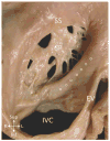
Multi - fenestrated septum primum (SP) or cribriform fossa ovalis. EV Eustachian valve, IVC inferior vena cava; SS septum secundum; o - muscular base of atrial septum.
Figure 4
Figure 4
Opened heart with ASD1. A - The fossa ovalis (FO) is intact as seen in the opened right atrium. The ASD1 is leftward of the fossa and immediately adjacent to the TV. A tongue of AV valve tissue (…..) covers the crest of the muscular ventricular septum. B - Septum primum (SP) is seen in the left atrium inserting (arrows) onto septum secundum (SS) and continuing to the edge of the ASD1. The superior (SL) and inferior (IL) cushion components of the anterior mitral leaflet are seen in the LV. CS - coronary sinus; LAA - left atrial appendage; RVO - right ventricular outflow; SVC - superior vena cava; ο - muscular base of the atrial septum.
Figure 5
Figure 5
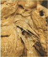
The superior (SL) and inferior (IL) components of the anterior mitral leaflet as well as the mural leaflet (ML) are seen in the opened LV in this heart with ASD1. The superior leaflet attaches only to the anterolateral papillary muscle (AL) and the inferior leaflet attaches only to the posteromedial papillary muscle (PM). The mural leaflet attaches to both. The cleft (white double headed arrow) is the space between the superior and inferior leaflets. Only the superior leaflet is in continuity with the aortic valve (Ao). Chordal attachments of this leaflet high in the outflow can cause subaortic stenosis.
Figure 6
Figure 6
Superior vena cava type of SVD. A - The right atrium (RA) is opened to show the junction with the superior vena cava (SVC). The left atrium (LA) can be seen through the SVD. Two right upper pulmonary veins (RUPV) drain to the SVC - RA junction near the defect. The fossa ovalis (FO) is seen inferior and leftward of the SVD. B - The same view showing a ‘patch’ (gray) covering the defect. Pulmonary venous blood (dashed red arrows) flows to the LA behind the patch while the blue solid arrow indicates SVC flow to the RA in front of the patch.
Figure 7
Figure 7
Posterior view of a heart with a CSD. The coronary sinus (CS) has been opened from the left superior vena cava (LSVC) to the right atrium (RA). The left atrium (LA) can be seen through the CSD, an opening in the wall between the CS and the LA. B - An echocardiogram in parasternal long - axis view showing a CSD (*) between the dilated coronary sinus (CS) and the left atrium (LA). Ao - aorta; LV - left ventricle.
Figure 8
Figure 8
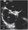
An echocardiogram in right sternal border view in a patient with multiple ASD2 (arrow heads). Ao - aorta; LA - left atrium; RA - right atrium.
Figure 9
Figure 9
A - An echocardiogram in apical 4 - chamber view in a patient with ASD1 (arrow). The defect is just above the closure plane of the AV valves. B - Color Doppler exam in the same view showing mitral regurgitation (++), most likely through the cleft in the anterior mitral leaflet. LA - left atrium; LV left ventricle; RA - right atrium; RV - right ventricle. (Reprinted from Valente et al. [11] with permission).
Figure 10
Figure 10
A - A MRI 3D SSFP axial view showing a superior vena cava (SVC) type of SVD (*). The right upper pulmonary vein (RUPV) drains to the SVC - right atrial junction near the SVD. The orifice of the RUPV into the left atrium (LA) (white arrow) is the interatrial communication. B - Sagittal projection of the same data set shows the defect (*) between the SVC - RA junction and the RUPV. Ao - aorta; IVC - inferior vena cava; LPV - left pulmonary vein; RPA - right pulmonary artery. (Reprinted from Valente et al. [11] with permission).
Figure 11
Figure 11
Transesophageal echocardiogram following device closure of an ASD 2. The left atrial arms of the device (white arrows) are seen in the left atrium (LA). RA - right atrium.
Figure 12
Figure 12
Kaplan Meier curve showing results of a randomized trial of surgical vs medical treatment of adults > 40 years old with ASD2 using a composite endpoint of cardiac - related death, heart failure, pulmonary or systemic embolism, recurrent pulmonary infection, sustained ventricular tachyarrhythmia and progression of pulmonary hypertension. (Reprinted from Attie et al. [16] with permission).
Figure 13
Figure 13
A heart with Ebstein anomaly. A - The right ventricle is opened showing the anterior tricuspid leaflet (AL) with multiple small fenestrations (*) and nearly continuous attachment of the anterior leaflet free edge to the RV wall. B - The right atrium and right ventricular inflow have been opened. The fossa ovalis (FO) and coronary sinus (CS) are seen in the right atrium. The black dotted line indicates the anatomic annulus of the tricuspid valve and the white dashed line the actual hinge point of the septal tricuspid leaflet. The space below the white line is the atrialized right ventricle. The black curved arrow indicates the superior rotation of the functional tricuspid annulus toward the RV outflow tract.
Figure 14
Figure 14
An obstructive form of Ebstein anomaly. The anterior tricuspid leaflet (AL) is continuously attached at the free edge to the right ventricular wall except inferiorly where there is a small orifice (*).
Figure 15
Figure 15
A 3 - dimensional echocardiogram in a patient with Ebstein anomaly viewed from the apex. The septal tricuspid leaflet did not delaminate from the septum (arrowhead) leaving a gap between the anterior (AL) and inferior (IL) leaflets. LV - left ventricle. (Image courtesy of Jerry Marx, MD, Children’s Hospital Boston).
Figure 16
Figure 16
MRI cine SSFP 4 - chamber projection in a patient with Ebstein anomaly showing the offset between the mitral (yellow arrow)and tricuspid (white arrow) insertions. The dotted line indicates the atrialized right ventricle. The functional right ventricle (RV) is small. LA - left atrium; LV - left ventricle; RA - right atrium.
Figure 17
Figure 17
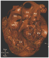
A 3D reconstruction of a CT scan of a waxed heart specimen with CTGA and ventricular septal defect. The right - sided right atrium (RA) is aligned with the right - sided left ventricle (LV) via the mitral valve (MV) and the left - sided left atrium with the right ventricle (RV) through the tricuspid valve (TV). The pulmonary artery (PA) is aligned with the LV and there is mitral - pulmonary fibrous continuity (white arrow). The aorta (Ao) is aligned with the RV and is separated from the tricuspid valve by subaortic conus (bracket). There is a large ventricular septal defect (*) in this specimen.
Figure 18
Figure 18
Kaplan Meier curve showing probability of freedom from systemic ventricular dysfunction in patients with CTGA. Group I had significant associated defects such as moderate or more tricuspid regurgitation, VSD, pulmonary stenosis. Group II had no or mild associated defects. (Reprinted from Graham et al. [63] with permission).
Figure 19
Figure 19
MRI cine SSFP frontal (A) and short - axis (B) views in a patient with CTGA. A - The right - sided right atrium (RA) is aligned with the right - sided left ventricle (LV) and the LV is aligned with the right - sided main pulmonary artery (MPA). There is dephasing in the MPA (arrowhead) due to pulmonary stenosis. The aorta (Ao) is superior and leftward and aligned with the left - sided right ventricle (RV). B - The LV, marked by the smooth septal surface and free wall papillary muscles, is anterior while the coarsely trabeculated RV is posterior. SVC superior vena cava.
Figure 20
Figure 20
Cartoons illustrating the atrial switch operation (A), and the arterial switch operation (B). (Reprinted from Valente et al. [11] with permission).
Figure 21
Figure 21
A - The opened pulmonary venous atrium in a heart after a Mustard atrial switch operation. The red curved arrows indicate flow from the right (RPV) and left pulmonary veins toward the tricuspid valve (TV) and right ventricle. The dashed blue curved arrows indicate flow from the superior vena cava (SVC) and inferior vena cava (IVC) behind the limbs of the baffle toward the mitral valve and left ventricle. B - The opened systemic venous atrium in the same heart showing the other side of the baffle with SVC and IVC flow (blue curved arrows) toward the mitral valve (MV). The left pulmonary veins (LPV) are seen posterior to the systemic venous atrium.
Figure 22
Figure 22
A - Left lateral view of the great arteries after an arterial switch operation. The main pulmonary artery (MPA) is anterior to the aorta (Ao). The left pulmonary artery (LPA) has been divided to show the inside of the aorta. The suture line (blue sutures) is evident between the ascending aorta (Ao) and the pulmonary root (*). The right coronary artery ostium (RCA) with surrounding button of aortic wall is seen on the right side of the aorta. B - A frontal view of the same heart showing the MPA and branches. The right pulmonary artery (RPA) passes posteriorly between the Ao and the superior vena cava (SVC). The divided LPA is to the left of the aorta (Ao).
Figure 23
Figure 23
A - a cartoon depicting the Rastelli operation for DTGA with ventricular septal defect (VSD) and pulmonary stenosis. The left ventricle (LV) is baffled to the aorta through the VSD and a conduit is placed from the right ventricle (RV) to the pulmonary artery. (Modified from Valente et al. [11] with permission). B - A heart specimen after a Rastelli operation shows the ventricular septal defect (double headed arrow) and the patch (Patch) directing the LV to the aorta (Ao). C - The opened RV showing the other side of the patch (Patch) and the junction of the conduit (C) with the RV.
Figure 24
Figure 24
MRI cine SSFP images in a patient after a Senning atrial switch operation. A - Right ventricular (RV) 2 - chamber view showing the two parts of the pulmonary venous atrium (PVA, PV) separated by the systemic venous atrium (*). The arrowhead indicates a baffle leak, a break in the interatrial baffle, allowing communication between the systemic and pulmonary venous atria. B - A 4 - chamber view in the plane indicated by the black dashed line in A. The connection (#) between the component of the pulmonary venous atrium (PV) that receives the pulmonary veins (RPV, LPV) and the supra - tricuspid portion (PVA) is seen in this view. (Reprinted from Valente et al. [11] with permission).
Figure 25
Figure 25
3D reconstruction of a CT exam of a waxed human heart with severe pulmonary venous pathway obstruction (*) after a Senning atrial switch operation. A - posterior view with the pulmonary veins removed to show the superior vena cava (SVC) and inferior vena cava (IVC) pathways joining the systemic venous atrium (SVA). The junction (*) between the portion of the pulmonary venous atrium that receives the right (RPV) and left (LPV) pulmonary veins and the supra - tricuspid portion of the pulmonary venous atrium (PVA) is severely stenosed. B - A cut in the plane indicated by the dashed white line in A showing the two portions of the pulmonary venous atrium. The IVC pathway (blue arrow) passes beneath the narrowed junction.
Figure 26
Figure 26
CMR exam in two patients after an arterial switch operation. A - Frontal view of a 3 - D reconstruction from a MRA showing the anterior pulmonary artery (MPA) with the branch pulmonary arteries (RPA, LPA) on either side of the ascending aorta. (Reprinted from Valente et al. [11] with permission). B - A 3D SSFP in axial projection showing the distorted contours and proximal narrowing of the branch pulmonary arteries (RPA, LPA). The ascending aorta (Ao) is seen between the branch pulmonary arteries and the superior vena cava (SVC) in front of the RPA.
Figure 27
Figure 27
CMR exam in a patient after a Rastelli operation. A - A cine SSFP short - axis cut through the ventricular septal defect (*) showing the flow path from the left ventricle (LV) to the aorta (Ao). B - A more apical cut showing the junction of the conduit (C) with the right ventricle (RV). C - A 3 - D reconstruction from the MRA showing the RV - pulmonary artery (PA) conduit (C) to the right of the Ao. The conduit is flattened by the chest wall.
Figure 28
Figure 28
3D reconstructions from a MRA performed in an adult patient with complex double outlet right ventricle who underwent repair in childhood. A - Left lateral view showing a Damus - Kaye - Stansel anastomosis (*) between the pulmonary root (PA) and the ascending aorta (AAo) because of severe subaortic stenosis (yellow arrow). The left ventricle (LV) was baffled to the pulmonary root (PA) through the ventricular septal defect. B - A conduit (C) was placed between the right ventricle (RV) and the pulmonary arteries. There is severe proximal left pulmonary artery (LPA) stenosis (white arrowhead). The irregularities in the anterior wall of the conduit (red arrows) are artifacts from sternal wires. RPA - right pulmonary artery.
Figure 29
Figure 29
Two hearts after repair of TOF with the right ventricle opened. A - This heart was operated in an earlier era when wide patch plasty of the right ventricular outflow was the standard. Note the large patch defined by the arrowheads over the outflow (blue curved arrow). The ventricular septal defect patch (VSD) is seen between the tricuspid valve (TV) and the outflow. B - The outflow patch (arrowheads) is much smaller in a heart operated more recently. The patch crosses the pulmonary annulus (white dotted line) and extends onto the left pulmonary artery (LPA).
Figure 30
Figure 30
A - Opened right ventricle (RV) in a patient with TOF and pulmonary atresia who underwent repair using a valved conduit. The RV outflow (blue curved arrow) was created from the ventriculotomy to which the conduit (C) was sewn. The ventricular septal defect patch (VSD) is seen extending above the tricuspid valve (TV). B - An anterior superior view of the same heart showing the connection of the valved conduit (C) to the main pulmonary artery (MPA) to the left of the aorta (Ao).
Figure 31
Figure 31
Cartoon showing the various types of aorto - pulmonary shunts that have been used over the past half century. The classical Blalock - Taussig shunt connects the subclavian artery opposite the side of the aortic arch end - to - side to the ipsilateral pulmonary artery. The modified Blalock - Taussig shunt is constructed by inserting a tube graft between the innominate artery or the proximal subclavian artery and the ipsilateral pulmonary artery. The Potts shunt is a side - to - side connection of the left pulmonary artery to the descending aorta. A Waterston shunt is a connection of the ascending aorta side - to - side to the right pulmonary artery. (Modified from Valente et al. [11] with permission).
Figure 32
Figure 32
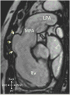
MRI 3D SSFP sagittal plane image in a patient late after repair of TOF. The right ventricle (RV) is dilated and an outflow tract aneurysm (yellow arrows) has formed. LPA - left pulmonary artery; MPA - main pulmonary artery. (Reprinted from Valente et al. [11] with permission).
Figure 33
Figure 33
A - MRI cine SSFP short - axis image in a patient late after repair of TOF. The RV is dilated due to severe pulmonary insufficiency from wide patch plasty of the RV outflow. B - Graph of instantaneous flow velocity vs time calculated from a phase contrast MR sequence prescribed across the right ventricular outflow. Antegrade flow is shown above baseline (red) and retrograde or regurgitant flow below (blue). The area under each portion of the curve indicates volume flow which is used to calculate the regurgitant fraction.
Figure 34
Figure 34
MRI short - axis images showing delayed gadolinium enhancement in a patient after repair of TOF. A - A cut at the level of the right ventricular (RV) outflow showing delayed enhancement of the outflow patch (yellow arrows). The patient suffered a perioperative inferior infarction of the left ventricle (LV) indicated by delayed enhancement (white arrows). B - A cut through the LV outflow showing delayed enhancement of the patch closing the ventricular septal defect (red arrows). The LV inferior infarction is seen in this cut as well (white arrows).
Figure 35
Figure 35
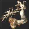
3D reconstruction of a MRA in an adult patient after repair of TOF with pulmonary atresia. Multiple collateral arteries were unifocalized with the central pulmonary arteries and connected to the right ventricle (RV) using a conduit (C). There is severe proximal stenosis (white arrowhead) of the right pulmonary artery (RPA). LPA left pulmonary artery.
Figure 36
Figure 36
A - The opened right ventricle (RV) in a heart following repair of TOF and implantation of a bioprosthesis (yellow arrow) in the pulmonary position. The ventricular septal defect patch (VSD) is completely endothelialized. The RV anterior wall (white arrowheads) is thin and fibrotic. This tissue is often removed when RV remodeling is performed during valve implantation. B - The bifurcation of the pulmonary artery showing the branches (RPA, LPA) and the arterial surface of the bioprosthesis (yellow arrow).
Figure 37
Figure 37
Kaplan Meier survival curve for hospital survivors of TOF repair. Note the inflection in the curve at about 25 years. The late attrition rate is nearly 4 times the early rate. (Reprinted from Nollert et al. [128] with permission).
Figure 38
Figure 38
Types of Fontan operations likely to be seen in adult congenital centers today. A - The atriopulmonary connection was abandoned in the mid - 1980s because of dilatation of the right atrium predisposing to thrombosis and atrial arrhythmias. B - lateral tunnel is used widely in part because of the ease of fenestration of this type. C - extracardiac conduit is also widely used because it can be performed without bypass and does not create extensive atrial suture lines. This type is more difficult to fenestrate. (Modified from Valente et al. [11] with permission).
Figure 39
Figure 39
Frontal view of a heart after an atriopulmonary Fontan operation. A conduit (C) was used to join the right atrium (RA) and the pulmonary arteries. The right (RPA) and left (LPA) branches are seen arising from the junction with the conduit. The aorta (Ao) is anterior and leftward in this heart with Double Inlet Left Ventricle (DILV). There is a calcified patch (P) on the right AV valve to prevent flow of venous blood from the RA into the systemic ventricle.
Figure 40
Figure 40
A - MRI cine SSFP coronal view in a patient with an atriopulmonary connection (blue curved arrow). The right atrium (RA) is dilated and the atrial septum bulges into the left atrium (LA). B - MRI 3D SSFP axial view in a patient with functionally one ventricle (V) after a lateral tunnel Fontan operation. The lateral tunnel (Lat T) is seen in cross - section within the atrium. A patch (white arrows) separates the tunnel from the remainder of the atrium (LA). IVC - inferior vena cava; LPA - left pulmonary artery; SVC - superior vena cava. (Reprinted from Valente et al. [11] with permission).
Figure 41
Figure 41
MRI 3D SSFP frontal views in a patient with hypoplastic left heart syndrome after extracardiac conduit Fontan operation. A - The Glenn anastomosis between the superior vena cava (SVC) and the right pulmonary artery (RPA) is seen. The junction of the extracardiac conduit (EC) with the inferior aspect of the RPA is seen but the rest of the conduit is out of the plane. The neo - aorta (Neo - Ao) is to the left of the SVC. B - The conduit (EC), SVC and left pulmonary artery (LPA) are seen but the RPA is out of plane. As frequently seen the LPA is smaller than the RPA. Note that the conduit is separate from the atrium.
Figure 42
Figure 42
Discrete juxtaductal coarctation. The posterior shelf (Sh) is seen just distal to the left subclavian artery (LSCA). The ductus arteriosus (DA) is opposite the posterior shelf. Note the fleshy, corrugated appearance of the ductus tissue, completely different from either the main pulmonary artery (MPA) or the descending aorta (DAo). The distal arch (*) is mildly narrow. AAo - ascending aorta; LPA - left pulmonary artery.
Figure 43
Figure 43
Left lateral view of a 3D reconstruction from a MRA in an adult with severe coarctation (white arrowhead). Note the large collateral vessels (yellow arrow) and the dilated internal mammary arteries (white arrows). AAo - ascending aorta; LA - left atrium.
Figure 44
Figure 44
Left lateral angiograms in an adult patient with recurrent coarctation (white arrow) before (A) and after (B) balloon dilation.

Similar articles

Cited by

References

    1. Hoffman JI, Kaplan S, Liberthson RR. Prevalence of congenital heart disease. Am Heart J. 2004;147:425–439. - PubMed
    1. Marelli AJ, Gurvitz M. From numbers to guidelines. Prog Cardiovasc Dis. 2011;53:239–246. - PubMed
    1. Lai W, Mertens L, Cohen M, Geva T. Echocardiography in Pediatric and Congenital Heart Disease: From Fetus to Adult. Wiley-Blackwell; 2009.
    1. Rosas M, Attie F. Atrial septal defect in adults. Timely Top Med Cardiovasc Dis. 2007;11:E34. - PubMed
    1. Najm HK, Williams WG, Chuaratanaphong S, Watzka SB, Coles JG, et al. Primum atrial septal defect in children: early results, risk factors, and freedom from reoperation. Ann Thorac Surg. 1998;66:829–835. - PubMed

LinkOut - more resources