Review
. 2013 Dec;38(12):1929-1940.
doi: 10.1016/j.progpolymsci.2013.05.001.

Efficiency of bulk-heterojunction organic solar cells

Affiliations
Review

Efficiency of bulk-heterojunction organic solar cells

M C Scharber et al. Prog Polym Sci. 2013 Dec.

Abstract

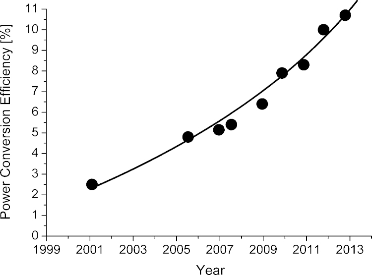
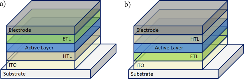
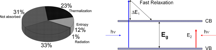
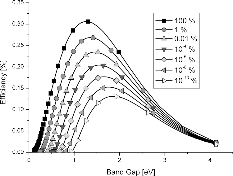
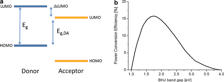
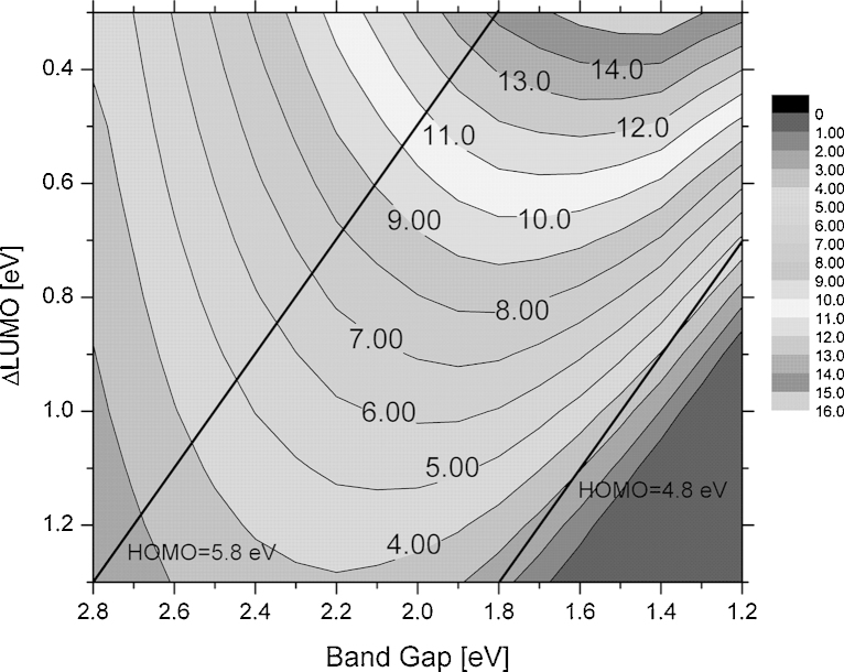
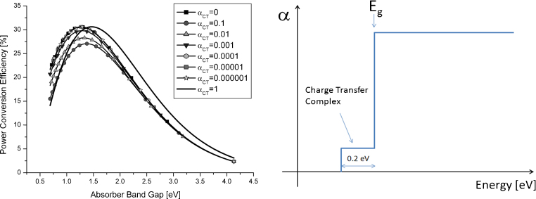
During the last years the performance of bulk heterojunction solar cells has been improved significantly. For a large-scale application of this technology further improvements are required. This article reviews the basic working principles and the state of the art device design of bulk heterojunction solar cells. The importance of high power conversion efficiencies for the commercial exploitation is outlined and different efficiency models for bulk heterojunction solar cells are discussed. Assuming state of the art materials and device architectures several models predict power conversion efficiencies in the range of 10-15%. A more general approach assuming device operation close to the Shockley-Queisser-limit leads to even higher efficiencies. Bulk heterojunction devices exhibiting only radiative recombination of charge carriers could be as efficient as ideal inorganic photovoltaic devices.

Keywords: Bulk heterojunction solar cell; Organic solar cell; Power conversion efficiency.


Figures

Fig. 1
Fig. 1
Certified record power conversion efficiencies of single junction organic solar cells published in Progress in Photovoltaics. The first point in the graph (year 2001) is not listed in any efficiency table.
Fig. 2
Fig. 2
Examples for donor and acceptor materials used in bulk heterojunction solar cells. (a) Poly[(4,4′-bis(2-ethylhexyl)dithieno[3,2-b:2′,3′-d]silole)-2,6-diyl-alt-(4,7-bis(2-thienyl)-2,1,3-benzothiadia-zole)-5,5′-diyl] , (b) poly-(3-hexylthiophene-2,5-diol), (c) diketopyrrolopyrrole based oligomer , (d) 5,5′-bis{(4-(7-hexylthiophen-2-yl)thiophen-2-yl)-[1,2,5]thiadiazolo[3,4-c]pyridine}-3,3′-di-2-ethylhexylsilylene-2,2′-bithiophene, (e) [6,6]-phenyl-C61-butyric acid methyl , (f) bisadduct analog [6,6]-phenyl-C61-butyric acid methyl and (g) indene-C60-bisadduct.
Fig. 3
Fig. 3
Energy level diagram of a donor acceptor system; IP is the ionization potentials, is the electron affinity. The arrow between the LUMO-levels indicates the photoinduced electron transfer which is the first step for generating free charge carriers.
Fig. 4
Fig. 4
Schematic cross-section of nanomorphologies of bulk heterojunction solar cells. (a) Fine mixture of donor and acceptor molecules, (b) bilayer arrangement, (c) ideal morphology of a bulk heterojunction solar cells and (d) typical morphology of a solution processes device.
Fig. 5
Fig. 5
Different device architectures of bulk heterojunction solar cells. (a) Standard device design with the cathode on top of the device stack and (b) inverted device architecture with the cathode located on the transparent substrate.
Fig. 6
Fig. 6
Illustration of the different losses in an ideal solar cell, photon energy larger or smaller the absorber gap (left); power conversion efficiency losses according to the Shockley–Queisser analysis. ΔE1 is the photon access energy which is lost due to fast relaxation of the photoexcited charge carrier. Photons with energy E2 smaller than the band gap are not absorbed by the semiconductor.
Fig. 7
Fig. 7
Shockely–Queisser efficiency limit for solar cells with different radiative recombination contributions (from 100% down to 10−10% radiative recombination) .
Fig. 8
Fig. 8
(a) Schematic diagram of the energetic levels of a donor acceptor system. Eg,DA is often called the effective band gap and (b) power conversion efficiency versus the absorber band gap derived assuming a loss of 1 eV per thermalized charge carrier .
Fig. 9
Fig. 9
Contour plot showing the power conversion efficiency of a bulk heterojunction solar cell with PCBM as acceptor material (LUMO level 4.3 eV). For the calculation an EQE of 80%, a FF of 75% and an open circuit voltage according to Eq. (1) was used. Black lines indicate constant HOMO levels of 5.8 eV and 4.8 eV respectively.
Fig. 10
Fig. 10
(a) Profile of an ideal absorber with a weak and 0.2 eV broad charge transfer absorption feature. (b) Power conversion efficiency of a solar cell with a absorption profile (a) and different absorptions strength (CT) of the charge transfer state , .

References

    1. Shaheen S.E., Brabec C.J., Sariciftci N.S. 2.5% Efficient organic plastic solar cells. Appl Phys Lett. 2001;78:841–843.
    1. Service R. Outlook brightens for plastic solar cells. Science. 2011;332:293. - PubMed
    1. Green M.A., Emery K., King D.L., Hishikawa Y., Warta W. Solar cell efficiency tables (version 28) Prog Photovolt Res Appl. 2006;14:455–461.
    1. Green M.A., Emery K., Hishikawa Y., Warta W. Solar cell efficiency tables (version 31) Prog Photovolt Res Appl. 2008;16:435–440.
    1. Green M.A., Emery K., Hishikawa Y., Warta W. Solar cell efficiency tables (version 34) Prog Photovolt Res Appl. 2009;17:320–326.