. 2013 Nov;40(11):112901.
doi: 10.1118/1.4823793.

Integrated ultrasound and magnetic resonance imaging for simultaneous temperature and cavitation monitoring during focused ultrasound therapies

Affiliations

Integrated ultrasound and magnetic resonance imaging for simultaneous temperature and cavitation monitoring during focused ultrasound therapies

Costas D Arvanitis et al. Med Phys. 2013 Nov.

Abstract

Purpose: Ultrasound can be used to noninvasively produce different bioeffects via viscous heating, acoustic cavitation, or their combination, and these effects can be exploited to develop a wide range of therapies for cancer and other disorders. In order to accurately localize and control these different effects, imaging methods are desired that can map both temperature changes and cavitation activity. To address these needs, the authors integrated an ultrasound imaging array into an MRI-guided focused ultrasound (MRgFUS) system to simultaneously visualize thermal and mechanical effects via passive acoustic mapping (PAM) and MR temperature imaging (MRTI), respectively.

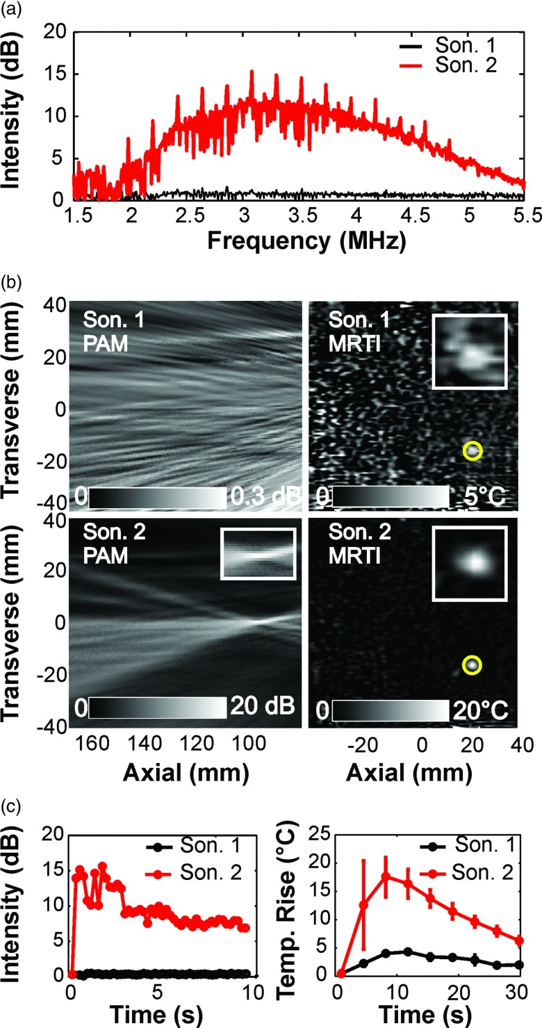
Methods: The system was tested with an MRgFUS system developed for transcranial sonication for brain tumor ablation in experiments with a tissue mimicking phantom and a phantom-filled ex vivo macaque skull. In experiments on cavitation-enhanced heating, 10 s continuous wave sonications were applied at increasing power levels (30-110 W) until broadband acoustic emissions (a signature for inertial cavitation) were evident. The presence or lack of signal in the PAM, as well as its magnitude and location, were compared to the focal heating in the MRTI. Additional experiments compared PAM with standard B-mode ultrasound imaging and tested the feasibility of the system to map cavitation activity produced during low-power (5 W) burst sonications in a channel filled with a microbubble ultrasound contrast agent.

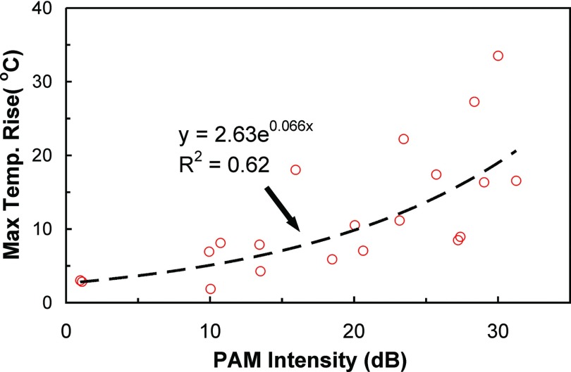
Results: When inertial cavitation was evident, localized activity was present in PAM and a marked increase in heating was observed in MRTI. The location of the cavitation activity and heating agreed on average after registration of the two imaging modalities; the distance between the maximum cavitation activity and focal heating was -3.4 ± 2.1 mm and -0.1 ± 3.3 mm in the axial and transverse ultrasound array directions, respectively. Distortions and other MRI issues introduced small uncertainties in the PAM∕MRTI registration. Although there was substantial variation, a nonlinear relationship between the average intensity of the cavitation maps, which was relatively constant during sonication, and the peak temperature rise was evident. A fit to the data to an exponential had a correlation coefficient (R(2)) of 0.62. The system was also found to be capable of visualizing cavitation activity with B-mode imaging and of passively mapping cavitation activity transcranially during cavitation-enhanced heating and during low-power sonication with an ultrasound contrast agent.

Conclusions: The authors have demonstrated the feasibility of integrating an ultrasound imaging array into an MRgFUS system to simultaneously map localized cavitation activity and temperature. The authors anticipate that this integrated approach can be utilized to develop controllers for cavitation-enhanced ablation and facilitate the optimization and development of this and other ultrasound therapies. The integrated system may also provide a useful tool to study the bioeffects of acoustic cavitation.


Figures

Figure 1
Figure 1
Experimental setup. (Left) Diagram (approximately to scale) showing arrangement of the quality assurance phantom, ultrasound imaging array, and MRI coil within the 30 cm diameter hemisphere transducer of the MRgFUS system. A brass reflector oriented at 45° to the face of the imaging array directed the ultrasound imaging plane parallel to the focal plane of the MRgFUS device. The imaging array was connected to a research ultrasound imaging engine located outside of the MRI room. The face of the imaging array was 13 cm away from the geometric focus of the MRgFUS system—a distance selected to accommodate a human head in future works. (Right) Sagittal and axial MRI of a phantom-filled ex vivo macaque skull. In this example, a channel in the phantom was created for experiments sonicating an ultrasound contrast agent.
Figure 2
Figure 2
(a) Individual passive acoustic maps obtained during cavitation-enhanced heating in a phantom-filled macaque skull before and after background correction. With this correction, maps where broadband emissions were observed were normalized to a map obtained during an earlier sonication at a lower power level at the same target, according to Eq. 4. The highest power sonication where broadband signals were not observed was used for this normalization. (b) Data are shown here relative to the maximum intensity in the corrected and uncorrected maps. The correction reduced signals appearing in front of and behind the focal activity in the axial direction. These data were obtained during the sonications shown in Fig. 7.
Figure 3
Figure 3
Acoustic emissions, MRTI, and passive cavitation maps obtained simultaneously during two successive sonications at a target in the quality assurance phantom. (a) The power spectra of the cavitation activity obtained during the two sonications. During the second sonication (acoustic power: 90 W), substantial broadband and harmonic emissions were observed. No activity was observed during the first sonication (70 W) (b) Maps showing the intensity of the cavitation activity (left) and the focal heating (right) for these two sonications. At this target, the second sonication resulted in significant cavitation activity and a marked increase in heating; no cavitation activity was evident during the first sonication, and only a small temperature rise was observed. The axial and transverse directions of the ultrasound imaging array with respect to the images are noted. (c) The maximum signal in the cavitation maps (left) and the average temperature rise in the focal region (right) as a function of time. The cavitation activity began at the start of the sonication, and was sustained throughout. Note the rapid and marked temperature increase and the large error bars when cavitation activity was induced.
Figure 4
Figure 4
Plot showing the maximum temperature rise measured via MRTI during 20 sonications in the quality assurance phantom as a function of the corresponding maximum intensity measured in the passive cavitation maps. A fit of the data to an exponential (dashed line) is also shown.
Figure 5
Figure 5
Registration accuracy of the MRTI and cavitation mapping, and resolution of the passive imaging. (a) Histogram showing the mismatch in the locations of the maximum heating and cavitation activity after registration of the MRI and ultrasound imaging coordinate spaces. Histograms for the transverse and axial directions of the ultrasound imaging array from all the individual cavitation maps. Cavitation activity was not detected in 46 of the 676 cavitation maps; they were excluded from this analysis. Zero indicates exact colocalization; negative values indicate that the location of the maximum cavitation activity was further to the left of the heating in the axial direction or above it in the transverse direction in the images in (d). (b) and (c) Histograms showing the axial and transverse resolutions of the cavitation maps, which varied from location to location depending on the location of the focal region and the frequency content of the recorded acoustic emissions. The effective frequency of the acoustic emissions ranged from 2.8 to 3.4 MHz (mean value: 3.1 MHz). The distance of the sonicated targets from the array varied between 10 and 15 cm. The highest resolution was obtained from cavitation maps from the targets closest to the array that also had highest effective frequency. (d) Fusion of cavitation and temperature maps. Yellow circles are centered at the point of maximum heating, and white circles are centered at the maximum pixel value of the cavitation maps. The red area shows the 90% contour of the cavitation maps. Note how the length of the apparent cavitation activity is reduced when the focal region was steered closer to the imaging array.
Figure 6
Figure 6
Focal heating in MRTI and cavitation activity mapped with passive and active ultrasound imaging. (Top) MRTI acquired during sonication of two targets in the quality assurance phantom. (Middle and bottom) The corresponding passive cavitation maps and B-mode images acquired during sonication at these targets. The yellow circles are centered on the maximum temperature elevation; red crosses indicate the location of maximum signal in the passive cavitation maps. Acoustic emissions arising from the first target were observed when sonicating the second target (arrows). The acoustic power levels in the first and second target were 50 and 100 W, respectively. Note that the four ultrasound images were collected during different sonications at the powers mentioned above; the focal heating in MRTI was similar in each case. The axial and transverse directions of the ultrasound imaging array with respect to the images are noted. The appearance of the void in focal heating was presumably due to heat-induced PRF changes that were greater than the receive bandwidth per voxel in the sequence used for MRTI. Such changes caused the signal in the heated area to shift by one voxel in the frequency encode direction. Phase wrap may have also occurred.
Figure 7
Figure 7
Transcranial PAM and MRTI acquired simultaneously during cavitation-enhanced heating in a phantom-filled ex vivo macaque skull. (a) MRTI, cavitation maps, and the fusion of the two modalities obtained during two successive 100 W sonications at different locations. Note that cavitation activity at the location of the first sonication target is evident in PAM acquired during the second sonication. This activity was not observed in MRTI. Cavitation activity and heating were also observed in a location near the skull during the first sonication (dashed yellow circle). Other voxels that appeared to be heated in the MRTI were noise resulting from low signal magnitude (such as in the skull) or other artifacts; temperature vs time plots of those voxels were random and clearly not heating. The phase- and frequency-encoding directions in the MRTI were swapped between sonications at targets 1 and 2. The large artifact evident at the bottom of the MRTI for target 2 (white arrow) appeared when the phase-encoding direction was oriented left/right. Swapping phase- and frequency-encoding also introduced distortions and apparent shifts in the image; note the apparent change in position of the skull between targets 1 and 2 (white dashed line). (b) The average temperature rise in a 3 × 3 voxel region around the focal spot and the respective acoustic emissions for the two sonicated targets. For the acoustic emissions, the average power spectra are shown.
Figure 8
Figure 8
Transcranial passive cavitation mapping during sonication on a channel filled with diluted ultrasound contrast agent in a phantom-filled ex vivo macaque skull. (a) Region with cavitation activity superimposed on a T1-weighted MR image showing the channel that was filled with ultrasound contrast agent. The region where the average signal in the cavitation maps was within 5% of the maximum activity is shown in red. The location of this activity overlapped with the position of the channel. The corresponding power spectrum for this sonication is shown below (b). Low-level broadband emissions were observed along with substantial harmonic activity.

References

    1. ter Haar G., “Therapeutic applications of ultrasound,” Prog. Biophys. Mol. Biol. 93, 111–129 (2007).10.1016/j.pbiomolbio.2006.07.005 - DOI - PubMed
    1. Martin E., Jeanmonod D., Morel A., Zadicario E., and Werner B., “High-intensity focused ultrasound for noninvasive functional neurosurgery,” Ann. Neurol. 66, 858–861 (2009).10.1002/ana.21801 - DOI - PubMed
    1. Jones E. L. et al., “Randomized trial of hyperthermia and radiation for superficial tumors,” J. Clin. Oncol. 23, 3079–3085 (2005).10.1200/JCO.2005.05.520 - DOI - PubMed
    1. Moros E. G., Penagaricano J., Novak P., Straube W. L., and Myerson R. J., “Present and future technology for simultaneous superficial thermoradiotherapy of breast cancer,” Int. J. Hyperthermia 26, 699–709 (2010).10.3109/02656736.2010.493915 - DOI - PMC - PubMed
    1. Dromi S. et al., “Pulsed-high intensity focused ultrasound and low temperature-sensitive liposomes for enhanced targeted drug delivery and antitumor effect,” Clin. Cancer Res. 13, 2722–2727 (2007).10.1158/1078-0432.CCR-06-2443 - DOI - PMC - PubMed

Publication types