. 2014 Oct;27(5):419-24.
doi: 10.1007/s10334-013-0425-0. Epub 2013 Dec 15.

ViP MRI: virtual phantom magnetic resonance imaging

Affiliations
Free PMC article

ViP MRI: virtual phantom magnetic resonance imaging

Hervé Saint-Jalmes et al. MAGMA. 2014 Oct.
Free PMC article

Abstract

Object: The ability to generate reference signals is of great benefit for quantitation of the magnetic resonance (MR) signal. The aim of the present study was to implement a dedicated experimental set-up to generate MR images of virtual phantoms.

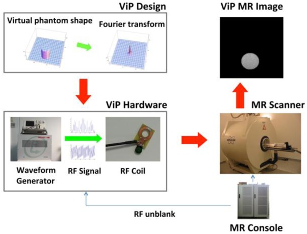
Materials and methods: Virtual phantoms of a given shape and signal intensity were designed and the k-space representation was generated. A waveform generator converted the k-space lines into a radiofrequency (RF) signal that was transmitted to the MR scanner bore by a dedicated RF coil. The k-space lines of the virtual phantom were played line-by-line in synchronization with the magnetic resonance imaging data acquisition.

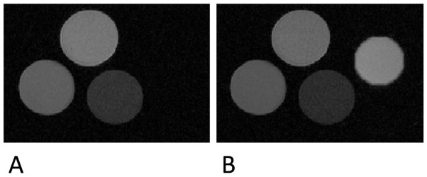
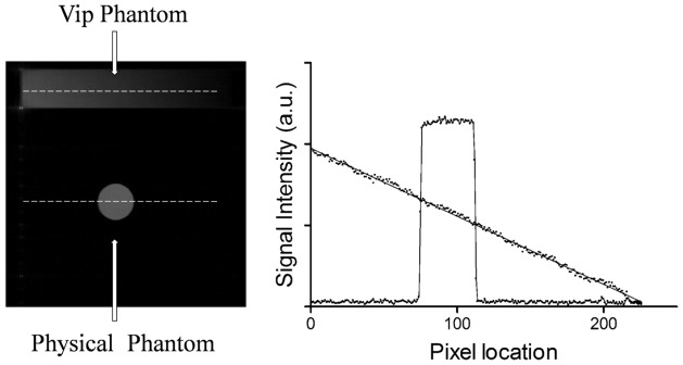
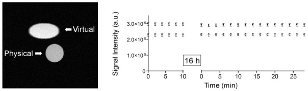
Results: Virtual phantoms of complex patterns were reproduced well in MR images without the presence of artifacts. Time-series measurements showed a coefficient of variation below 1% for the signal intensity of the virtual phantoms. An excellent linearity (coefficient of determination r (2) = 0.997 as assessed by linear regression) was observed in the signal intensity of virtual phantoms.

Conclusion: Virtual phantoms represent an attractive alternative to physical phantoms for providing a reference signal. MR images of virtual phantoms were here generated using a stand-alone, independent unit that can be employed with MR scanners from different vendors.


Figures

Figure 1
Figure 1
Schematics of the experimental apparatus for Virtual Phantom (ViP) MRI. The first step consists in designing the phantom shape and generating the k-space representation. The waveform generator of the ViP hardware converts the simulated k-space lines into RF signal that is transmitted by a dedicated RF coil, positioned in the scanner bore in proximity of the scanner RF coil. The ViP RF signal is synchronized with the MR scanner data acquisition by the RF unblank signal from the MR console. An oscilloscope was also part of the ViP hardware, in order to verify that the timings were properly implemented.
Figure 2
Figure 2
Proof of concept of Virtual Phantom (ViP) MRI. The MR image of three tubes filled with agar + gadolinium at different concentrations (physical phantom) is shown in panel A. The same acquisition was repeated with the ViP signal (panel B). The ViP tube is well represented and can provide a reference value for the MR signal intensity. Imaging acquisition parameters were: repetition time = 500 ms, echo time = 20 ms, matrix size of 256×256 and dwell time = 20 μs.
Figure 3
Figure 3
Multi-echo MR imaging of virtual and physical phantoms. The physical phantom consists of three tubes filled with agar + gadolinium at different concentrations. Signal intensities from ROIs selected in the virtual and physical phantoms are plotted as a function of TE. The monoexponential fit to the data is represented by the continuous line. The virtual phantom was designed with a transverse relaxation time equal to 60 ms. The transverse relaxation time obtained from data fitting was 59.9 ± 1.4 ms.
Figure 4
Figure 4
The MR image (left panel) and the plot of the signal intensity (right panel) of a virtual and physical phantom. The signal intensity illustrated on the plot is taken along the profiles represented by the dashed lines on the image. The virtual phantom was designed in the shape of a ramp, with linear signal intensity. For the virtual phantom, the continuous line on the plot represents the linear regression of the signal intensity values. For the real phantom, the continuous line is the connecting line of the signal intensity values.
Figure 5
Figure 5
A spin-echo MR image (left panel) and the plot of the signal intensity at different times (right panel) of a virtual (symbols ‘●’) and physical phantom (symbols ‘○’). MR images were acquired every two minutes and an interval of 16 hours was taken between the two series of measurements. The signal stability of the virtual phantom is comparable to that of the physical phantom, with a coefficient of variation below 1%.
Figure 6
Figure 6
The MR image of a quality-control phantom and a virtual phantom (the logo of the European Society for Magnetic Resonance in Medicine and Biology, ESMRMB). The ESMRMB logo was purposely designed to overlap with the physical phantom. The elaborate shape of the ESMRMB logo (the letters and the incomplete ring-shaped curve) is well reproduced.

References

    1. Barantin L, Le Pape A, Akoka S. A new method for absolute quantitation of MRS metabolites. Magn Reson Med. 1997;38(2):179–182. - PubMed
    1. Michel N, Akoka S. The application of the ERETIC method to 2D-NMR. J Magn Reson. 2004;168(1):118–123. - PubMed
    1. Martínez-Bisbal MC, Monleon D, Assemat O, Piotto M, Piquer J, Llácer JL, Celda B. Determination of metabolite concentrations in human brain tumour biopsy samples using HR-MAS and ERETIC measurements. NMR Biomed. 2009;22(2):199–206. - PubMed
    1. Albers MJ, Butler TN, Rahwa I, Bao N, Keshari KR, Swanson MG, Kurhanewicz J. Evaluation of the ERETIC method as an improved quantitative reference for 1H HR-MAS spectroscopy of prostate tissue. Magn Reson Med. 2009;61(3):525–532. - PMC - PubMed
    1. Ziarelli F, Viel S, Sanchez S, Cross D, Caldarelli S. Precision and sensitivity optimization of quantitative measurements in solid state NMR. J Magn Reson. 2007;188(2):260–266. - PubMed

Publication types