. 2014 Mar;111(6):1165-82.
doi: 10.1152/jn.00493.2013. Epub 2013 Dec 18.

Motor learning of novel dynamics is not represented in a single global coordinate system: evaluation of mixed coordinate representations and local learning

Affiliations

Motor learning of novel dynamics is not represented in a single global coordinate system: evaluation of mixed coordinate representations and local learning

Max Berniker et al. J Neurophysiol. 2014 Mar.

Abstract

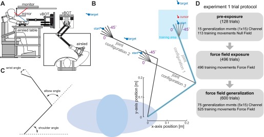
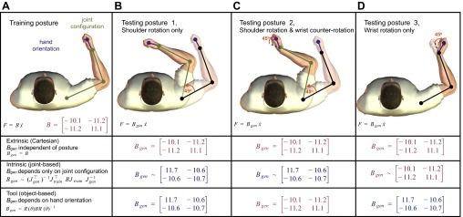
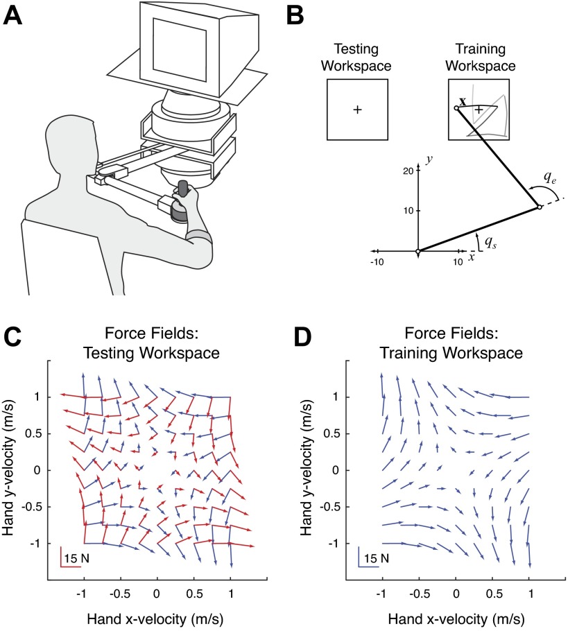
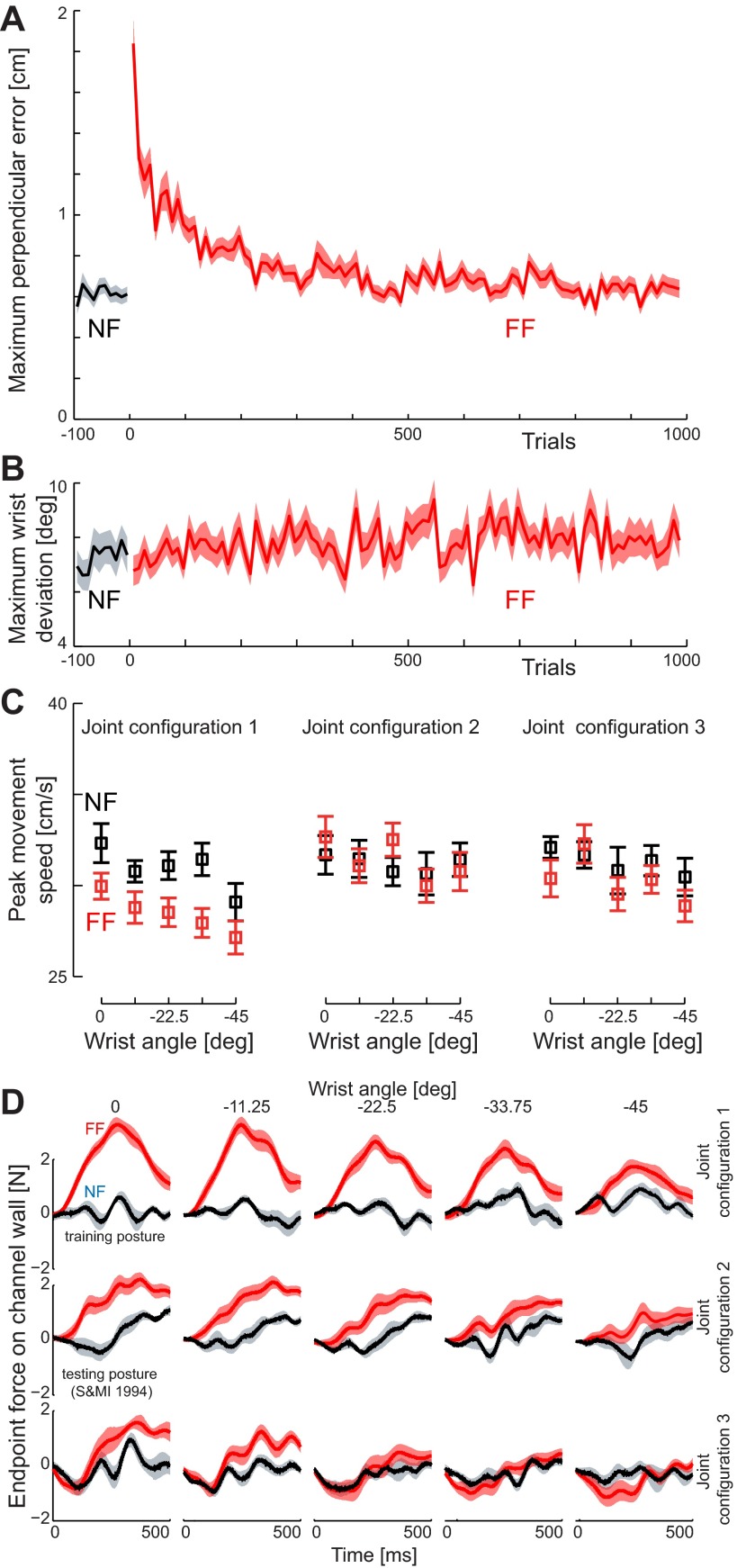
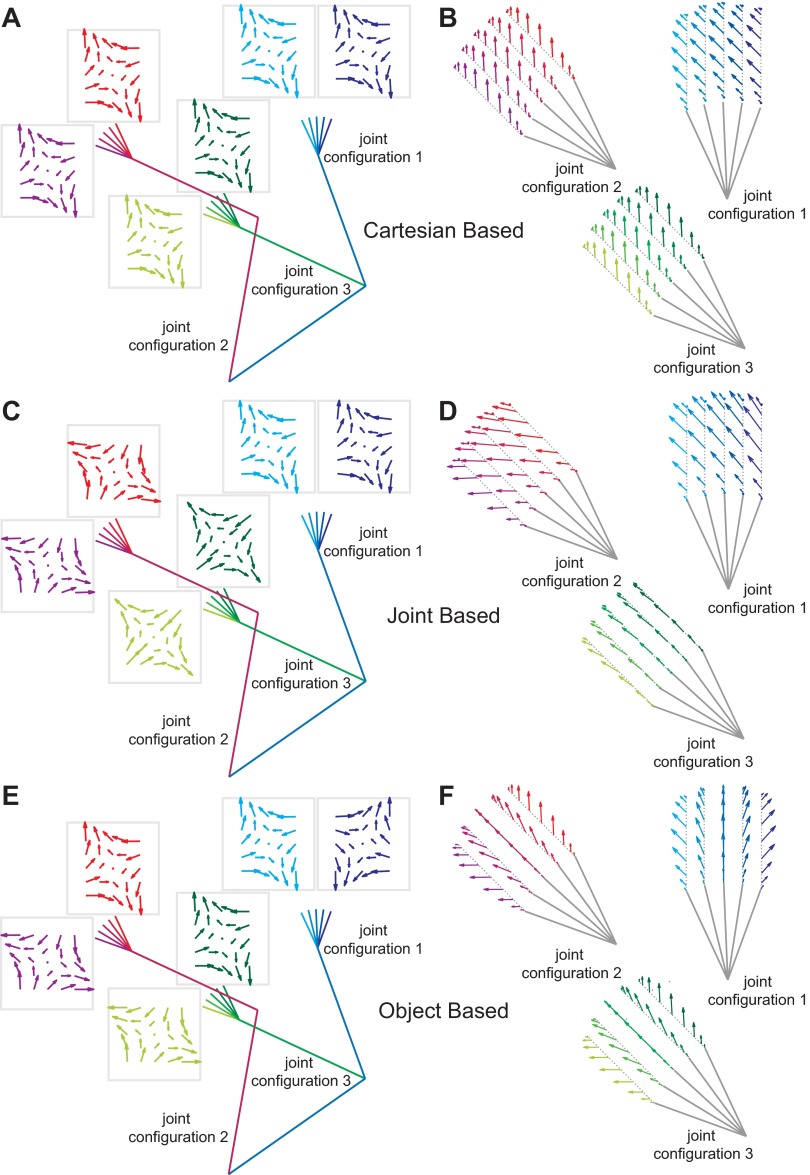
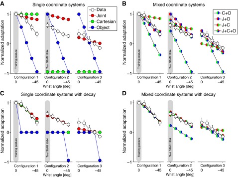
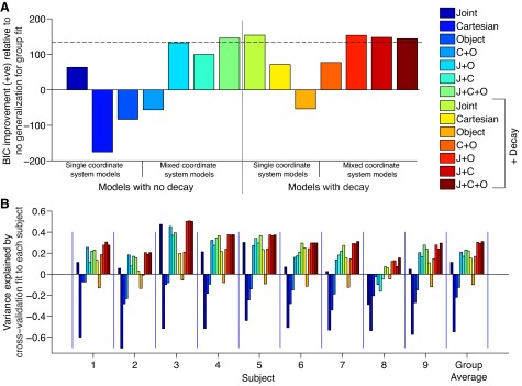
Successful motor performance requires the ability to adapt motor commands to task dynamics. A central question in movement neuroscience is how these dynamics are represented. Although it is widely assumed that dynamics (e.g., force fields) are represented in intrinsic, joint-based coordinates (Shadmehr R, Mussa-Ivaldi FA. J Neurosci 14: 3208-3224, 1994), recent evidence has questioned this proposal. Here we reexamine the representation of dynamics in two experiments. By testing generalization following changes in shoulder, elbow, or wrist configurations, the first experiment tested for extrinsic, intrinsic, or object-centered representations. No single coordinate frame accounted for the pattern of generalization. Rather, generalization patterns were better accounted for by a mixture of representations or by models that assumed local learning and graded, decaying generalization. A second experiment, in which we replicated the design of an influential study that had suggested encoding in intrinsic coordinates (Shadmehr and Mussa-Ivaldi 1994), yielded similar results. That is, we could not find evidence that dynamics are represented in a single coordinate system. Taken together, our experiments suggest that internal models do not employ a single coordinate system when generalizing and may well be represented as a mixture of coordinate systems, as a single system with local learning, or both.

Keywords: coordinate frames; internal models; intralimb generalization; motor adaptation; motor control.


Figures

Fig. 1.
Fig. 1.
Experimental protocol for experiment 1. A: experimental setup in which subjects grasp the handle of a robotic manipulandum. Also shown is the air sled table that subjects rested their arm on and the monitor-mirror system that provided visual feedback. B: training and generalization postures and movements. The posture is composed of the joint configuration (shoulder and elbow angles) and the hand orientation (which is varied by changing the wrist angle). The training posture (blue arm) defined the 15 × 15 cm training workspace (blue shaded square). All training movements were performed with the hand oriented in the workspace as shown. The transfer of learning to other locations was examined at 15 postures (gray arms). In joint configuration 1, the hand could be oriented at 5 angles and a 10-cm generalization movement was performed directly ahead at each posture. The start, target, and cursor for the generalization movement at the middle hand orientation are shown. Similarly, 5 other hand orientations (each associated with a single generalization movement direction) were used for joint configuration 2 and joint configuration 3. Again, the movement for the middle hand orientation is illustrated with the start and target locations. All generalization movements were performed in a simulated mechanical channel in which the force produced by the subjects could be measured against the channel wall. The orientation of the hand in Cartesian space was always consistent for both start and end targets for any given movement. C: illustration of the 3 joint angles, which are calculated relative to the previous segment orientation. D: outline of the 3 stages of experiment 1 detailing the number and type of trials that occur in each stage.
Fig. 2.
Fig. 2.
Schematic of the effect of the representation of dynamics on the pattern of generalization to novel postures. A: subjects learn to compensate for novel dynamics (external force field B) in a training posture defined by the joint configuration (shoulder and elbow angles) and the hand orientation. The generalization can then be tested at different limb postures in order to probe the coordinate frame in which the representation of the dynamics has been learned. Each of these 3 possibilities, extrinsic, intrinsic, and tool based, make different predictions depending on the posture. B: in testing posture 1, the arm has been rotated around the shoulder by 45°. While the predicted generalization of the force field (Bgen) for an extrinsic (Cartesian based) representation is unchanged, the predictions from both intrinsic and object-based representations are different (but identical to each other). This limb posture is equivalent to that examined in Shadmehr and Mussa-Ivaldi (1994). Note that it is not possible to distinguish object-based from intrinsic representations using only this posture. C: in testing posture 2, the wrist angle has been counterrotated by 45° (relative to testing posture 1) such that the hand orientation is identical to the training posture. Now the predictions based on extrinsic and object-based representations are identical but different from those based on an intrinsic representation. Note that θ in the rotation matrix corresponds to hand orientation in external space and not to wrist angle. D: finally, when only the hand orientation is changed by 45° (testing posture 3) from the training posture, the extrinsic and intrinsic predictions are identical and only the prediction from the object-based representation is different. For the intrinsic (joint based) predictions, the ∼ indicates that we model the arm here as a 2-joint system for illustrative purposes (although all modeling and analysis is performed with a 3-joint model; see materials and methods for details).
Fig. 3.
Fig. 3.
Experimental protocol for experiment 2. A: subjects gripped the handle of a robotic manipulandum with their arm in a sling (not shown) such that movements were in a plane approximately aligned with their shoulder. B: all reaching movements were made in the training and testing workspaces. These were located at a fixed distance from each subject's right shoulder (the origin). By measuring the location of their hand (the robot handle), their shoulder and elbow angles could be computed. All subjects adapted to a force field in the training workspace and were then probed for generalization in the testing workspace. C and D: the intrinsically and extrinsically defined force fields (red and blue vectors, respectively) were identical in the training workspace but nearly orthogonal in the testing workspace.
Fig. 4.
Fig. 4.
Learning of the force field dynamics in experiment 1. A: maximum perpendicular error (MPE) is plotted against the trial number for training movements in the initial null field (NF, black) and in the skew viscous force field (FF, red). The mean (solid line) and SE (shaded region) are shown across all subjects. B: mean peak wrist rotation (±SE) across all subjects is shown for the movements in the null field (black) and skew viscous force field (red) during the training movements. Note that no increase in wrist motion is seen when the force field is introduced. C: peak speed in the channel trials at each of the 15 test postures. The mean peak speed (±SE) across all subjects is shown for the movements in the null field (black) and skew viscous force field (red) during the test movements. Results are plotted as a function of the change in wrist angle rather than absolute hand orientation. D: force generalization. The mean (±SE) force trace during the channel movements is shown for movements in both prelearning (black) and late exposure (red) in the test movement trials.
Fig. 5.
Fig. 5.
Predictions of the 3 models for experiment 1. A: in a Cartesian-based generalization the force field remains constant in Cartesian space despite the change in limb geometry. The force field plots show force vectors as a function of hand velocity (as in Fig. 3D), with each of the 6 fields corresponding to the 3 joint configurations and the 2 extreme hand orientations (wrist flexion and extension) for these configurations. The color codes of the force fields are matched to their corresponding posture. B: the forces expected for Cartesian-based generalization are shown for a minimum jerk movement for the 5 hand orientations in the 3 configurations. Each configuration had 1 movement direction selected to be maximally informative in distinguishing between the 3 coordinate systems. In this case, the forces do not depend on the hand orientation or joint configuration but only on movement direction. C: for joint-based generalization the expected force field changes for each joint configuration. Because of the noninvertibility of the Jacobian for the 3-joint model, we use here the model based on the virtual segment (see materials and methods), which leads to very similar force predictions. D: joint-based generalization (virtual segment) predicts a different pattern of generalization for each joint configuration that is also different from the Cartesian generalization (B). The hand orientation affects the direction of the expected forces slightly. E: for object-based generalization, the expected force fields should rotate with the hand orientation. Therefore, as the hand orientation rotates by 45° (through any combination of wrist, elbow, or shoulder rotation), so does the expected force field. F: the forces expected for object-based generalization vary with hand orientation and are strikingly different from Cartesian (B) or joint-based (D) generalization.
Fig. 6.
Fig. 6.
Adaptation on generalization trials and model fits. A: mean adaptation (±SE across subjects) as function of generalization postures (Data): model fits for the joint-based, Cartesian-based, and object-based coordinate system models. All predictions and the subjects' data are normalized to 1 at the training posture. B: fits of the mixture of coordinate system models. The weighting of the components was required to sum to 1 C: fits of the single-coordinate system models with decay. D: the first of the mixture of coordinate system models with decay.
Fig. 7.
Fig. 7.
Model comparisons. A: Bayesian information criterion (BIC) improvement for each of the models relative to no generalization (that is, a model in which the force is zero at all the generalization postures). Dashed line shows the cutoff for models that are not considered to be distinguishable in terms of their performance from the best model. B: leave-one-out cross-validation analysis. For each subject we show the variance explained for each model when fit to the average of the remaining subjects' data. The final column shows the average of the variance explained across subjects. The model color code is as in A.
Fig. 8.
Fig. 8.
Average hand paths during baseline null field reaching in experiment 2. For each subject, the last 200 trials were processed accordingly: the starting location for each hand path was translated to the origin (in x and y) and then temporally aligned to the point in time where the velocity first reached the value of 0.1 m/s. These paths were sorted according to reach direction and feedback condition. Displayed are the across-subject averages and SDs of reaches made without visual feedback in the testing workspace (A) and the training workspace (B) along with the locations of the targets (drawn to scale).
Fig. 9.
Fig. 9.
Average hand paths during adaptation trials in experiment 2. Similar to Fig. 8, using all 1,000 trials of adaptation, paths were translated to the origin, temporally aligned, and sorted according to target and feedback condition and force field. Displayed are the across-subject averages for no-vision, force field trials during the first (A), second (B), third (C), and last (D) 250 trials of adaptation.
Fig. 10.
Fig. 10.
Average hand paths during no-vision, null field, catch trials in experiment 2. Similar to Fig. 9, paths are translated to origin, temporally aligned, and sorted to target. Displayed are the across-subject averages for the catch trials in the first (A), second (B), third (C), and last (D) 250 trials of adaptation.
Fig. 11.
Fig. 11.
Average hand paths during generalization trials in the testing workspace in experiment 2. For each subject (regardless of training group), all generalization reaches are translated to origin, temporally aligned, and sorted according to target and force field. Displayed are the across-subject averages for the trials with the intrinsically defined field (10 subjects; A), the extrinsically defined field (10 subjects; B), and the null field (4 subjects; C).
Fig. 12.
Fig. 12.
Individual subject performance during generalization trials in experiment 2 as measured with correlation ρ (see materials and methods). A: average correlations during adaptation trials without visual feedback. B: average correlations during adaptation trials with visual feedback. C: average correlations during the generalization block. Trials in intrinsic, extrinsic, and null fields are grouped separately for each subject. All error bars are SEs. Statistical significance: *P < 0.05, **P < 0.01.
Fig. 13.
Fig. 13.
Subject performance during generalization trials in experiment 2: performance metrics of maximum perpendicular deviation from a straight reach to the target (A), angular deviation from a straight reach (B), normalized path length (C), and correlation with position and velocity of baseline reaches (D). Left: across-subject average measures during baseline (null field), averaged across extrinsic and intrinsic groups (gray bars show training workspace, then testing workspace; error bars are SEs). Center: 250-trial bins of adaptation for both groups along with the null field catch trials (averaged across both groups). Right: across-subject averages for generalization trials (error bars are SEs).

References

    1. Ahmed AA, Wolpert DM, Flanagan JR. Flexible representations of dynamics are used in object manipulation. Curr Biol 18: 763–768, 2008 - PMC - PubMed
    1. Berniker M, Kording K. Estimating the sources of motor errors for adaptation and generalization. Nat Neurosci 11: 1454–1461, 2008 - PMC - PubMed
    1. Berniker M, Kording KP. Estimating the relevance of world disturbances to explain savings, interference and long-term motor adaptation effects. PLoS Comput Biol 7: e1002210, 2011 - PMC - PubMed
    1. Brayanov JB, Press DZ, Smith MA. Motor memory is encoded as a gain-field combination of intrinsic and extrinsic action representations. J Neurosci 32: 14951–14965, 2012 - PMC - PubMed
    1. Burgess JK, Bareither R, Patton JL. Single limb performance following contralateral bimanual limb training. IEEE Trans Neural Syst Rehabil Eng 15: 347–355, 2007 - PubMed

Publication types

LinkOut - more resources