

Microfluidic Valves Made From Polymerized Polyethylene Glycol Diacrylate
- PMID: 24357897
- PMCID: PMC3864702
- DOI: 10.1016/j.snb.2013.10.008
Microfluidic Valves Made From Polymerized Polyethylene Glycol Diacrylate
Abstract
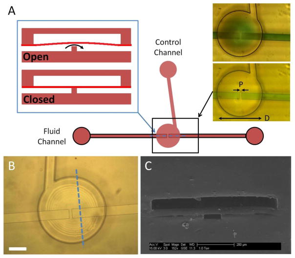
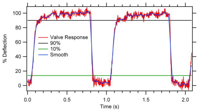
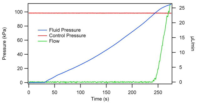
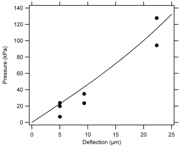
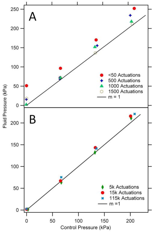
Pneumatically actuated, non-elastomeric membrane valves fabricated from polymerized polyethylene glycol diacrylate (poly-PEGDA) have been characterized for temporal response, valve closure, and long-term durability. A ~100 ms valve opening time and a ~20 ms closure time offer valve operation as fast as 8 Hz with potential for further improvement. Comparison of circular and rectangular valve geometries indicates that the surface area for membrane interaction in the valve region is important for valve performance. After initial fabrication, the fluid pressure required to open a closed circular valve is ~50 kPa higher than the control pressure holding the valve closed. However, after ~1000 actuations to reconfigure polymer chains and increase elasticity in the membrane, the fluid pressure required to open a valve becomes the same as the control pressure holding the valve closed. After these initial conditioning actuations, poly-PEGDA valves show considerable robustness with no change in effective operation after 115,000 actuations. Such valves constructed from non-adsorptive poly-PEGDA could also find use as pumps, for application in small volume assays interfaced with biosensors or impedance detection, for example.
Keywords: membrane valve; non-adsorptive polymer; non-elastomeric polymer; pneumatic actuation; poly-PEGDA; valve characterization; valve response.
Figures
Similar articles
-
3D printed microfluidic devices with integrated valves.Biomicrofluidics. 2015 Jan 13;9(1):016501. doi: 10.1063/1.4905840. eCollection 2015 Jan. Biomicrofluidics. 2015. PMID: 25610517 Free PMC article.
-
3D-Printed Microfluidic One-Way Valves and Pumps.Micromachines (Basel). 2023 Jun 23;14(7):1286. doi: 10.3390/mi14071286. Micromachines (Basel). 2023. PMID: 37512597 Free PMC article.
-
Thermally-actuated microfluidic membrane valve for point-of-care applications.Microsyst Nanoeng. 2021 Jun 15;7:48. doi: 10.1038/s41378-021-00260-3. eCollection 2021. Microsyst Nanoeng. 2021. PMID: 34567761 Free PMC article.
-
Materials and manufacturing perspectives in engineering heart valves: a review.Mater Today Bio. 2019 Dec 5;5:100038. doi: 10.1016/j.mtbio.2019.100038. eCollection 2020 Jan. Mater Today Bio. 2019. PMID: 32211604 Free PMC article. Review.
-
[Bio-artificial organs: cardiac applications].Verh K Acad Geneeskd Belg. 2004;66(4):246-52. Verh K Acad Geneeskd Belg. 2004. PMID: 15553097 Review. Dutch.
Cited by
-
High density 3D printed microfluidic valves, pumps, and multiplexers.Lab Chip. 2016 Jul 7;16(13):2450-8. doi: 10.1039/c6lc00565a. Epub 2016 May 31. Lab Chip. 2016. PMID: 27242064 Free PMC article.
-
3D printed microfluidic devices with integrated valves.Biomicrofluidics. 2015 Jan 13;9(1):016501. doi: 10.1063/1.4905840. eCollection 2015 Jan. Biomicrofluidics. 2015. PMID: 25610517 Free PMC article.
-
3D printed high density, reversible, chip-to-chip microfluidic interconnects.Lab Chip. 2018 Feb 13;18(4):639-647. doi: 10.1039/c7lc01113j. Lab Chip. 2018. PMID: 29355276 Free PMC article.
-
A Comprehensive Review of Organ-on-a-Chip Technology and Its Applications.Biosensors (Basel). 2024 May 1;14(5):225. doi: 10.3390/bios14050225. Biosensors (Basel). 2024. PMID: 38785699 Free PMC article. Review.
-
Fabrication of Microfluidic Devices for Emulsion Formation by Microstereolithography.Molecules. 2021 May 10;26(9):2817. doi: 10.3390/molecules26092817. Molecules. 2021. PMID: 34068649 Free PMC article. Review.
References
-
- Arora A, Simone G, Salieb-Beugelaar GB, Kim JT, Manz A. Latest Developments in Micro Total Analysis Systems. Anal Chem. 2010;82:4830–47. - PubMed
-
- van Midwoud PM, Janse A, Merema MT, Groothuis GMM, Verpoorte E. Comparison of Biocompatibility and Adsorption Properties of Different Plastics for Advanced Microfluidic Cell and Tissue Culture Models. Anal Chem. 2012;84:3938–44. - PubMed
-
- Abgrall P, Gué AM. Lab-on-chip technologies: making a microfluidic network and coupling it into a complete microsystem—a review. J Micromech Microeng. 2007;17:R15–R49.
Grants and funding
LinkOut - more resources
Full Text Sources
Other Literature Sources