

Photonic crystal enhancement of a homogeneous fluorescent assay using submicron fluid channels fabricated by E-jet patterning
- PMID: 24376013
- PMCID: PMC4980434
- DOI: 10.1002/jbio.201300158
Photonic crystal enhancement of a homogeneous fluorescent assay using submicron fluid channels fabricated by E-jet patterning
Abstract
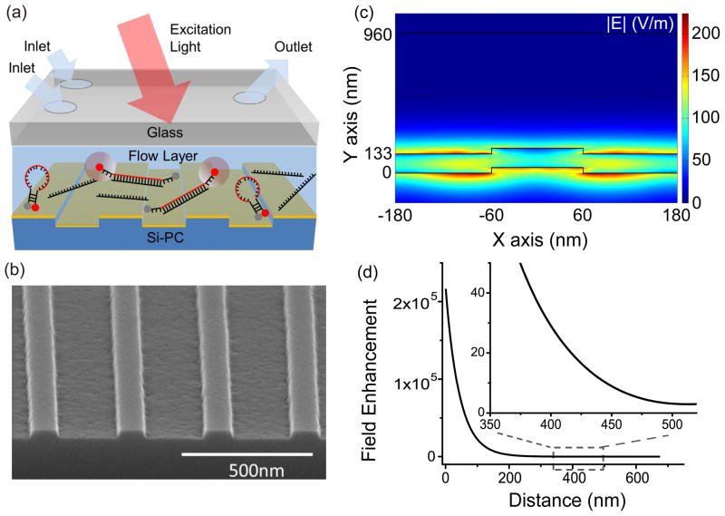
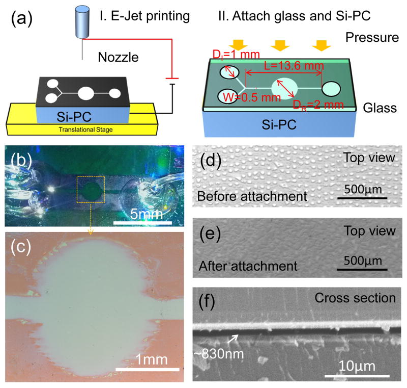
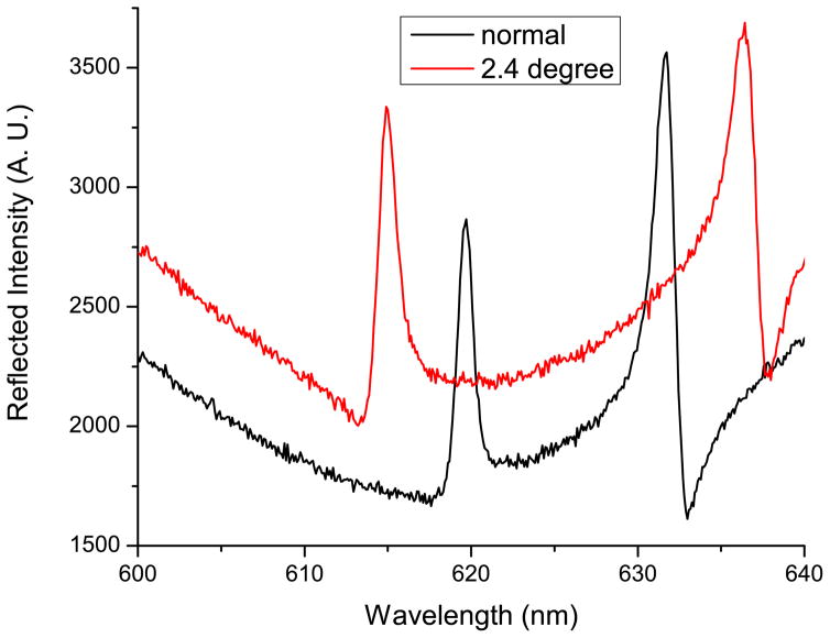
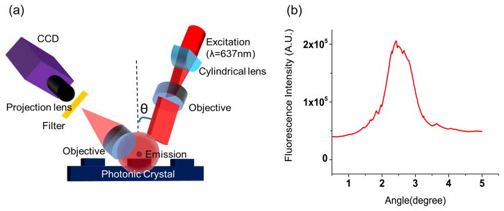
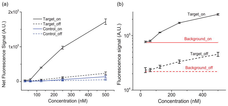
We demonstrate the enhancement of a liquid-based homogenous fluorescence assay using the resonant electric fields from a photonic crystal (PC) surface. Because evanescent fields are confined to the liquid volume nearest to the photonic crystal, we developed a simple approach for integrating a PC fabricated on a silicon substrate within a fluid channel with submicron height, using electrohydrodynamic jet (e-jet) printing of a light-curable epoxy adhesive to define the fluid channel pattern. The PC is excited by a custom-designed compact instrument that illuminates the PC with collimated light that precisely matches the resonant coupling condition when the PC is covered with aqueous media. Using a molecular beacon nucleic acid fluorescence resonant energy transfer (FRET) probe for a specific miRNA sequence, we demonstrate an 8× enhancement of the fluorescence emission signal, compared to performing the same assay without exciting resonance in the PC detecting a miRNA sequence at a concentration of 62 nM from a liquid volume of only ∼20 nL. The approach may be utilized for any liquid-based fluorescence assay for applications in point-of-care diagnostics, environmental monitoring, or pathogen detection.
Keywords: E-jet printing; enhanced fluorescence; homogeneous assay; photonic crystal; submicron channel.
Copyright © 2014 WILEY-VCH Verlag GmbH & Co. KGaA, Weinheim.
Figures
Similar articles
-
Sensitive detection of protein and miRNA cancer biomarkers using silicon-based photonic crystals and a resonance coupling laser scanning platform.Lab Chip. 2013 Oct 21;13(20):4053-64. doi: 10.1039/c3lc50579k. Epub 2013 Aug 20. Lab Chip. 2013. PMID: 23963502 Free PMC article.
-
Smart detection of microRNAs through fluorescence enhancement on a photonic crystal.Talanta. 2016 Apr 1;150:699-704. doi: 10.1016/j.talanta.2016.01.002. Epub 2016 Jan 16. Talanta. 2016. PMID: 26838461
-
Photonic crystal nanostructures for optical biosensing applications.Biosens Bioelectron. 2009 Aug 15;24(12):3688-92. doi: 10.1016/j.bios.2009.05.014. Epub 2009 May 20. Biosens Bioelectron. 2009. PMID: 19501502
-
Nanostructured surfaces and detection instrumentation for photonic crystal enhanced fluorescence.Sensors (Basel). 2013 Apr 26;13(5):5561-84. doi: 10.3390/s130505561. Sensors (Basel). 2013. PMID: 23624689 Free PMC article. Review.
-
Photon upconversion in homogeneous fluorescence-based bioanalytical assays.Ann N Y Acad Sci. 2008;1130:188-200. doi: 10.1196/annals.1430.027. Ann N Y Acad Sci. 2008. PMID: 18596348 Review.
Cited by
-
Recent Advances in Biosensing With Photonic Crystal Surfaces: A Review.IEEE Sens J. 2016 May 15;16(10):3349-3366. doi: 10.1109/JSEN.2015.2429738. Epub 2015 May 5. IEEE Sens J. 2016. PMID: 27642265 Free PMC article.
-
Two-dimensional photonic crystals for sensitive microscale chemical and biochemical sensing.Lab Chip. 2015 Feb 21;15(4):971-990. doi: 10.1039/c4lc01208a. Lab Chip. 2015. PMID: 25563402 Free PMC article. Review.
-
Emerging Biosensing Approaches for microRNA Analysis.Anal Chem. 2016 Jan 5;88(1):431-50. doi: 10.1021/acs.analchem.5b04679. Epub 2015 Dec 21. Anal Chem. 2016. PMID: 26654257 Free PMC article. Review.
References
-
- Lim LS, Hu M, Huang MC, Cheong WC, Gan ATL, Looi XL, Leong SM, Koay ESC, Li MH. Lab on a Chip. 2012;12(21):4388. - PubMed
Publication types
MeSH terms
Substances
Grants and funding
LinkOut - more resources
Full Text Sources
Other Literature Sources
