. 2014 Jan 9:7:51.
doi: 10.3389/fninf.2013.00051. eCollection 2014.

UNC-Utah NA-MIC framework for DTI fiber tract analysis

Affiliations

UNC-Utah NA-MIC framework for DTI fiber tract analysis

Audrey R Verde et al. Front Neuroinform. .

Abstract

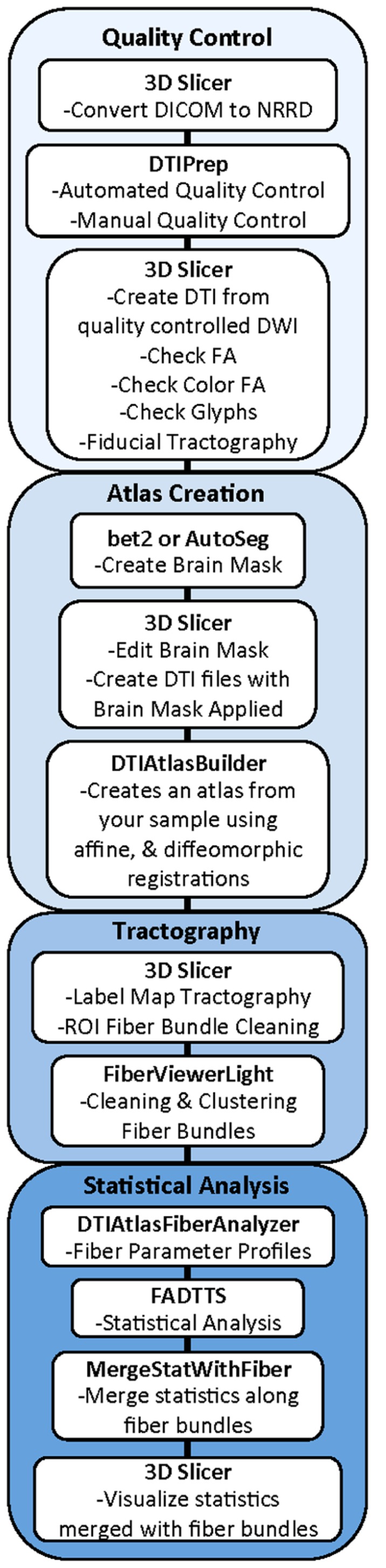
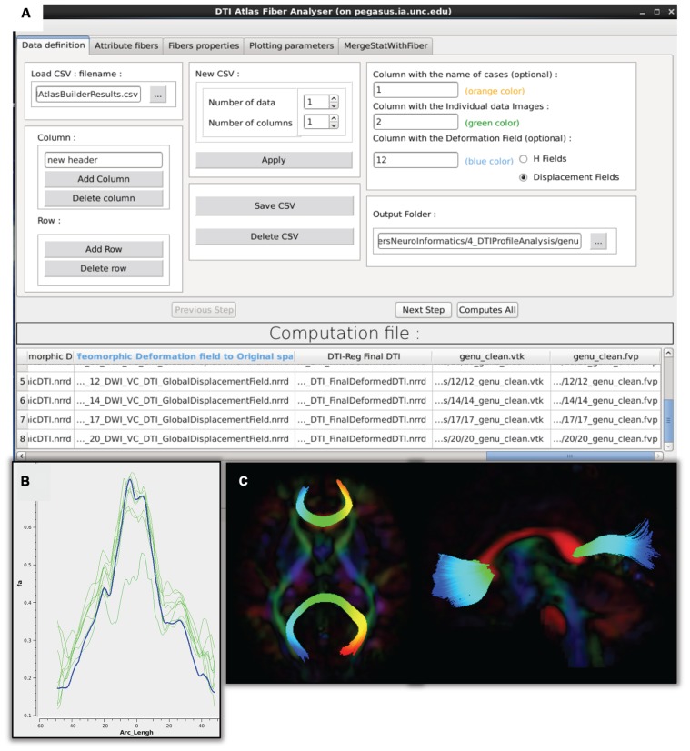
Diffusion tensor imaging has become an important modality in the field of neuroimaging to capture changes in micro-organization and to assess white matter integrity or development. While there exists a number of tractography toolsets, these usually lack tools for preprocessing or to analyze diffusion properties along the fiber tracts. Currently, the field is in critical need of a coherent end-to-end toolset for performing an along-fiber tract analysis, accessible to non-technical neuroimaging researchers. The UNC-Utah NA-MIC DTI framework represents a coherent, open source, end-to-end toolset for atlas fiber tract based DTI analysis encompassing DICOM data conversion, quality control, atlas building, fiber tractography, fiber parameterization, and statistical analysis of diffusion properties. Most steps utilize graphical user interfaces (GUI) to simplify interaction and provide an extensive DTI analysis framework for non-technical researchers/investigators. We illustrate the use of our framework on a small sample, cross sectional neuroimaging study of eight healthy 1-year-old children from the Infant Brain Imaging Study (IBIS) Network. In this limited test study, we illustrate the power of our method by quantifying the diffusion properties at 1 year of age on the genu and splenium fiber tracts.

Keywords: DTI atlas building; diffusion imaging quality control; diffusion tensor imaging; magnetic resonance imaging; neonatal neuroimaging; white matter pathways.


Figures

FIGURE 1
FIGURE 1
UNC-Utah NA-MIC DTI framework. Step 1 is quality control. Step 2 is atlas creation. Step 3 is interactive tractography. Step 4 is parameter profile creation and statistical analysis.
FIGURE 2
FIGURE 2
Schematic of DTI processing workflow. The input raw DWI data first undergoes vigorous quality control before the final conversion to DTI for Atlas building. Interactive tractography is performed on the Atlas. From these fiber bundles, diffusion parameter profiles are extracted and analyzed along with other study variables to determine significant interactions.
FIGURE 3
FIGURE 3
Artifacts encountered during quality control. (A) DWI artifact missed by automatic quality control run of DTIPrep, but caught in the visual quality control. You can see the horizontal lines running through this coronal view of the brain. Toward the top, almost an entire slice is missing. In cases like this, the gradient containing this artifact would be excluded from the saved DWI volume. (B) Axial and coronal view of DTI color fractional anisotropy (FA) volume. The large area of blue in the left frontal and temporal lobes indicates that a dominant direction artifact remains after DTIPrep quality control. Thus this artifact was too large to correct and this participant was excluded from analysis.
FIGURE 4
FIGURE 4
DTIAtlasBuilder steps, GUI, and registration progression. (A) DTIAtlasBuilder steps. Black solid arrows indicate transform computation. Blue solid arrows indicate transform application. Hollow black arrows indicate an averaging of transformed images. Before the Affine registration in step 1, fractional anisotropy (FA) is normalized so that FA intensity difference between subject images does not bias the atlas creation. The FA is also “filtered” to remove negative eigen values, which will adjust the resulting FA values to scale between zero and one. The transform computed in step 4 final resampling, diffeomorphic transform (B), is termed the Final (or Global) Displacement Field. It is this transform that is required to extract fiber tract profiles from each individual subject DTI when using DTIAtlasFiberAnalyzer later in the workflow. (B) DTIAtlasBuilder GUI. Here one can see the first tab with the input list of quality controlled and skull-stripped DTI volumes. Along the top of the GUI, the tabs for adjusting parameters and tool paths are visible. (C) Progression of the atlas building from a single participant volume to the affine atlas, and the final unbiased diffeomorphically registered DTI Atlas in the presented experimental pediatric population.
FIGURE 5
FIGURE 5
Slicer label map tractography. (A) Sagittal view of the corpus callosum genu label map in the Final DTI Atlas. (B) Resulting genu bundle fibers from label map tractography within 3D Slicer. The bundle is colored by FA values along the fibers with cooler colors indicating higher FA.
FIGURE 6
FIGURE 6
FiberViewerLight clustering, cleaning, and plane creation. (A) Example of genu fiber clustering based on the center of gravity. (B) In the left panel all of the fiber clustering algorithms are visible, as well as the different styles of computation (Classic vs Danielsson). In the right panel the plane function is visualized for the genu. This tool is used to set a plane of origin from which the fiber bundle will be parameterized for further analysis.
FIGURE 7
FIGURE 7
DTIAtlasFiberAnalyzer GUI. (A) In the first tab of this tool the input data is defined: the label for each participant, the original quality controlled skull-stripped DTI, and the GlobalDeformationField computed in Atlas Building. (B) After DTIAtlasFiberAnalyzer has sampled the intended diffusion parameters, DTI property profiles for individual images (green) and the DTI atlas (blue) can be visualized in the Plot Parameters tab. Inspecting these profiles allows for a different type of quality control of the atlas registrations. The FA profiles of the subjects (pictured here) should be similarly shaped to the atlas. (C) Visualization of the parameterized genu and splenium fibers in the axial and sagittal views. Fibers that have been correctly parameterized with DTIAtlasFIberAnalyzer via the origin plane will be colored by FiberLocationIndex (arclength) from red to blue. Red indicates low arclength and blue high arclengths. The corresponding profile plots of these genu and splenium fibers would run from the right to the left hemisphere.
FIGURE 8
FIGURE 8
Examples of possible plots from functional analysis of diffusion tensor tract statistics (FADTTS) and MergeStatWithFiber. (A) Plot the raw data. (B) Output of FDR corrected local-log p-values along the length of the fiber tract. (C) Separate beta plots for all of the covariates entered into the model and how they interact with each diffusion parameter. (D) Separate beta plots for how all the investigated diffusion parameters interact with each covariate in the model. For both beta plots, the filled in circles along the curves indicate areas of significance post FDR correction. (E) Visualization of local statistics along the tract with 3D Slicer. Specifically this image reflects the corrected local p-values for the interaction between Age and FA for the genu [(C) blue line, (D) red line]. All non-significant points are assigned a single value and color (dark blue here). Points that are significant then proceed from the next value on the color bar until the furthest end of the color bar. In the color bar shown, areas of significance are colored from cyan to red, with red areas indicating most significance. Any color bar available can be used.
FIGURE 9
FIGURE 9
A screenshot displaying our tools as available extensions in 3D Slicer (box highlighted to indicate our Slicer modules).

References

    1. Arsigny V., Fillard P., Pennec X., Ayache N. (2006). Log-Euclidean metrics for fast and simple calculus on diffusion tensors. Magn. Reson. Med. 56 411–421 10.1002/mrm.20965 - DOI - PubMed
    1. Avants B. B., Epstein C. L., Grossman M., Gee J. C. (2008). Symmetric diffeomorphic image registration with cross-correlation: evaluating automated labeling of elderly and neurodegenerative brain. Med. Image Anal. 12 26–41 10.1016/j.media.2007.06.004 - DOI - PMC - PubMed
    1. Corouge I., Fletcher P. T., Joshi S., Gilmore J. H., Gerig G. (2005). Fiber tract-oriented statistics for quantitative diffusion tensor MRI analysis. Med. Image Comput. Comput. Assist. Interv. 8 131–139 10.1016/j.media.2006.07.003 - DOI - PubMed
    1. Du G., Lewis M. M., Sen S., Wang J., Shaffer M. L., Styner M., et al. (2012). Imaging nigral pathology and clinical progression in Parkinson’s disease. Mov. Disord. 27 1636–1643 10.1002/mds.25182 - DOI - PMC - PubMed
    1. Faria A. V., Zhang J., Oishi K., Li X., Jiang H., Akhter K., et al. (2010). Atlas-based analysis of neurodevelopment from infancy to adulthood using diffusion tensor imaging and applications for automated abnormality detection. Neuroimage 52 415–428 10.1016/j.neuroimage.2010.04.238 - DOI - PMC - PubMed

LinkOut - more resources