

Latex micro-balloon pumping in centrifugal microfluidic platforms
- PMID: 24441792
- PMCID: PMC4254353
- DOI: 10.1039/c3lc51116b
Latex micro-balloon pumping in centrifugal microfluidic platforms
Abstract
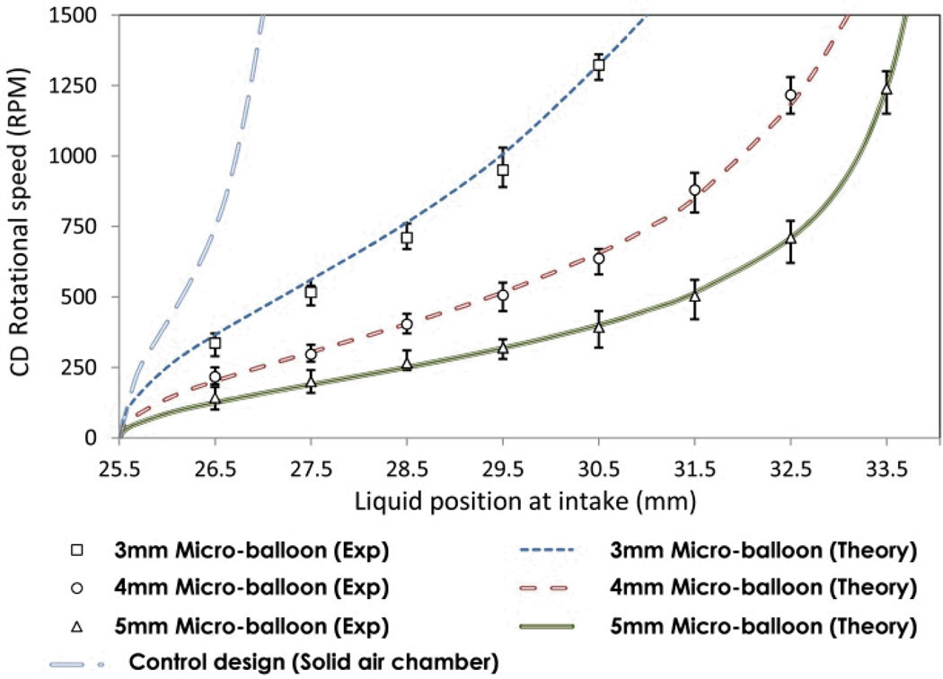
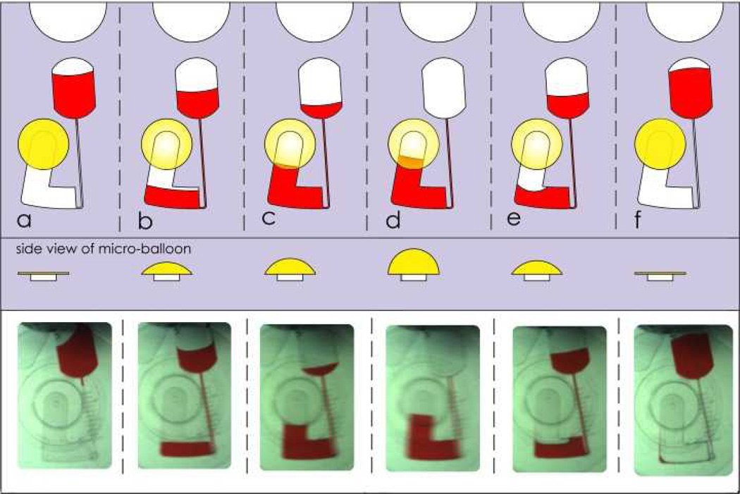
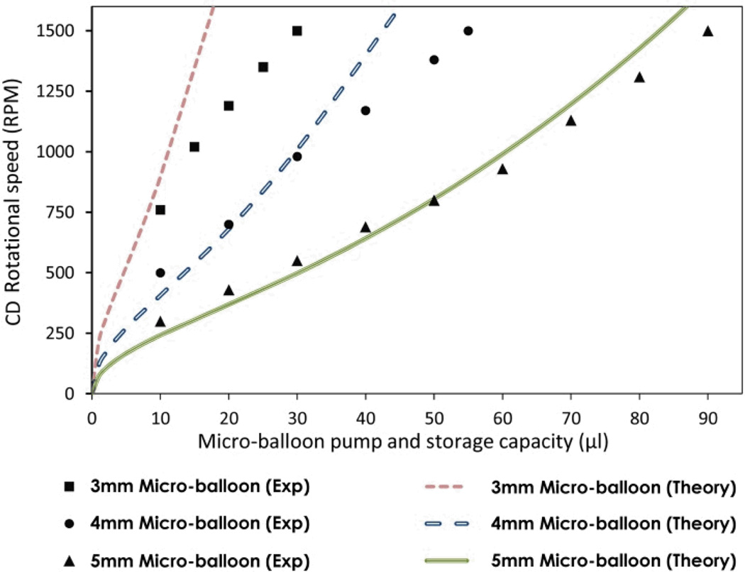
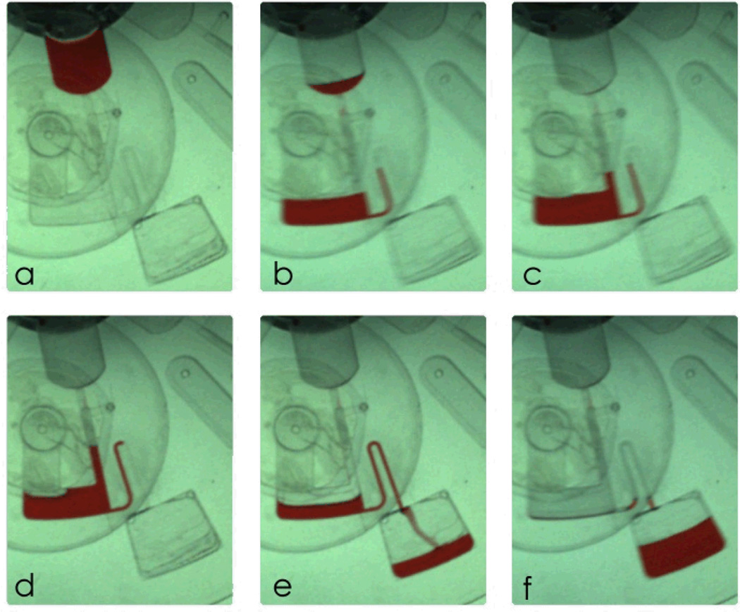
Centrifugal microfluidic platforms have emerged as point-of-care diagnostic tools. However, the unidirectional nature of the centrifugal force limits the available space for multi-step processes on a single microfluidic disc. To overcome this limitation, a passive pneumatic pumping method actuated at high rotational speeds has been previously proposed to pump liquid against the centrifugal force. In this paper, a novel micro-balloon pumping method that relies on elastic energy stored in a latex membrane is introduced. It operates at low rotational speeds and pumps a larger volume of liquid towards the centre of the disc. Two different micro-balloon pumping mechanisms have been designed to study the pump performance at a range of rotational frequencies from 0 to 1500 rpm. The behaviour of the micro-balloon pump on the centrifugal microfluidic platforms has been theoretically analysed and compared with the experimental data. The experimental data show that the developed pumping method dramatically decreases the required rotational speed to pump liquid compared to the previously developed pneumatic pumping methods. It also shows that within a range of rotational speed, a desirable volume of liquid can be stored and pumped by adjusting the size of the micro-balloon.
Figures

Similar articles
-
Development of Active Centrifugal Pump for Microfluidic CD Platforms.Micromachines (Basel). 2020 Jan 27;11(2):140. doi: 10.3390/mi11020140. Micromachines (Basel). 2020. PMID: 32012735 Free PMC article.
-
Reversible thermo-pneumatic valves on centrifugal microfluidic platforms.Lab Chip. 2015 Aug 21;15(16):3358-69. doi: 10.1039/c5lc00634a. Lab Chip. 2015. PMID: 26158597
-
Centrifugo-dynamic inward pumping of liquids on a centrifugal microfluidic platform.Lab Chip. 2012 Dec 21;12(24):5142-5. doi: 10.1039/c2lc40942a. Lab Chip. 2012. PMID: 23108455
-
Centrifugal microfluidic platforms: advanced unit operations and applications.Chem Soc Rev. 2015 Oct 7;44(17):6187-229. doi: 10.1039/c4cs00371c. Epub 2015 Jun 2. Chem Soc Rev. 2015. PMID: 26035697 Review.
-
Centrifugal microfluidics for biomedical applications.Lab Chip. 2010 Jul 21;10(14):1758-73. doi: 10.1039/b924109d. Epub 2010 May 28. Lab Chip. 2010. PMID: 20512178 Review.
Cited by
-
A micro-dispenser for long-term storage and controlled release of liquids.Nat Commun. 2019 Jan 14;10(1):189. doi: 10.1038/s41467-018-08091-z. Nat Commun. 2019. PMID: 30643146 Free PMC article.
-
Advances in passively driven microfluidics and lab-on-chip devices: a comprehensive literature review and patent analysis.RSC Adv. 2020 Mar 23;10(20):11652-11680. doi: 10.1039/d0ra00263a. eCollection 2020 Mar 19. RSC Adv. 2020. PMID: 35496619 Free PMC article. Review.
-
A film-lever actuated switch technology for multifunctional, on-demand, and robust manipulation of liquids.Nat Commun. 2022 Aug 20;13(1):4902. doi: 10.1038/s41467-022-32676-4. Nat Commun. 2022. PMID: 35987906 Free PMC article.
-
Density-Gradient Mediated Band Extraction of Leukocytes from Whole Blood Using Centrifugo-Pneumatic Siphon Valving on Centrifugal Microfluidic Discs.PLoS One. 2016 May 11;11(5):e0155545. doi: 10.1371/journal.pone.0155545. eCollection 2016. PLoS One. 2016. PMID: 27167376 Free PMC article.
-
A Novel Size-Based Centrifugal Microfluidic Design to Enrich and Magnetically Isolate Circulating Tumor Cells from Blood Cells through Biocompatible Magnetite-Arginine Nanoparticles.Sensors (Basel). 2024 Sep 18;24(18):6031. doi: 10.3390/s24186031. Sensors (Basel). 2024. PMID: 39338775 Free PMC article.
References
-
- Garcia-Cordero JL, Barrett LM, O’Kennedy R, Ricco AJ. Biomedical microdevices. 2010;12:1051–1059. - PubMed
-
- Haeberle S, Brenner T, Zengerle R, Ducrée J. Lab on a Chip. 2006;6:776–781. - PubMed
-
- Lee BS, Lee YU, Kim H-S, Kim T-H, Park J, Lee J-G, Kim J, Kim H, Lee WG, Cho Y-K. Lab Chip. 2010;11:70–78. - PubMed
-
- Madou M, Zoval J, Jia G, Kido H, Kim J, Kim N. Annu. Rev. Biomed. Eng. 2006;8:601–628. - PubMed
-
- Steigert J, Grumann M, Brenner T, Riegger L, Harter J, Zengerle R, Ducrée J. Lab Chip. 2006;6:1040–1044. - PubMed
Publication types
MeSH terms
Substances
Grants and funding
LinkOut - more resources
Full Text Sources
Other Literature Sources