. 2014:5:3089.
doi: 10.1038/ncomms4089.

A source of antihydrogen for in-flight hyperfine spectroscopy

Affiliations
Free PMC article

A source of antihydrogen for in-flight hyperfine spectroscopy

N Kuroda et al. Nat Commun. 2014.
Free PMC article

Abstract

Antihydrogen, a positron bound to an antiproton, is the simplest antiatom. Its counterpart-hydrogen--is one of the most precisely investigated and best understood systems in physics research. High-resolution comparisons of both systems provide sensitive tests of CPT symmetry, which is the most fundamental symmetry in the Standard Model of elementary particle physics. Any measured difference would point to CPT violation and thus to new physics. Here we report the development of an antihydrogen source using a cusp trap for in-flight spectroscopy. A total of 80 antihydrogen atoms are unambiguously detected 2.7 m downstream of the production region, where perturbing residual magnetic fields are small. This is a major step towards precision spectroscopy of the ground-state hyperfine splitting of antihydrogen using Rabi-like beam spectroscopy.


Figures

Figure 1
Figure 1. Schematic view of our experimental apparatus.
Arrows represent 1 m in each direction. Antiprotons delivered from the AD via the RFQD are trapped, electron-cooled and radially compressed in the MUSASHI. Moderated positrons from a 22Na source are prepared and cooled in the positron accumulator and then are transported to the cusp trap. The cusp trap consists of an MRE and superconducting anti-Helmholtz coils. After positrons are accumulated near the maximum magnetic field region, antiprotons are injected from the MUSASHI and mixed with positrons synthesizing antihydrogen atoms. Antihydrogen atoms in low-field-seeking states are focused downstream of the cusp trap due to the strong magnetic field gradient, while those high-field-seeking states are de-focused. Thus, a polarized antihydrogen beam is produced. On both sides of the cusp trap, scintillator modules labelled as I–IV are mounted, which are used to track charged pions produced by annihilation reactions. Downstream of the cusp trap a spectrometer line is placed, which involves a sextupole magnet and an antihydrogen detector.
Figure 2
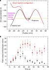
Figure 2. Antihydrogen synthesis.
(a) Illustration of the direct injection scheme, which is used to produce antihydrogen atoms. A positron plasma is confined and compressed at the centre of the nested well (black solid line). The potential is opened (red solid line) when antiprotons with low energy spread are injected into the positron plasma. The antiproton kinetic energy is adjusted to slightly higher than the potential energy of the positron plasma (yellow solid line), which ensures efficient mixing of antiprotons and positrons. To prolong the interaction time during mixing, an rf drive (not shown in the figure) is applied, which drives the axial oscillation of the antiprotons. (b) The number of antihydrogen atoms field-ionized downstream of the nested trap as a function of time. The filled black squares are from an experiment when direct injection was applied. The filled red circles represent results obtained from the rf-assisted direct injection scheme. Error bars show s.d. of the mean. By applying the rf drive the yield of field-ionized antihydrogen atoms was increased by a factor of 3.5.
Figure 3
Figure 3. Energy deposition by atoms and estimated number of atoms.
(a) Distributions of energy deposition in the BGO scintillator for the double coincidence condition (see the text). The distributions are normalized to one mixing cycle of 150 s. The unshaded histogram bordered by the thick blue line is obtained from scheme 1. The total data accumulation time was 4,950 s. The shaded histogram represents data obtained from the background runs, in a total time of 1,550 s. A clear difference is seen at energies higher than 40 MeV, indicating the observation of antihydrogen atoms. (b) The number of integrated events as a function of threshold energy, Eth, after subtraction of the background events. Filled squares are for scheme 1, filled triangles for scheme 2. Errors are propagated from the s.d. of the observed event numbers. (c) The estimated number of antihydrogen atoms that reached the BGO scintillator. The numbers are evaluated by calibrating the counts shown in b with the detection probability as a function of Eth predicted by GEANT4 simulation.

References

    1. Parthey C. G. et al.. Improved measurement of the hydrogen 1s–2s transition frequency. Phys. Rev. Lett. 107, 203001 (2011). - PubMed
    1. Ramsey N. Atomic hydrogen hyperfine structure experiments. InQuantum Electrodynamics ed. Kinoshita T. 673–695World Scientific (1990).
    1. Widmann E. et al.. Hyperfine structure measurements of antiprotonic helium and antihydrogen. InThe Hydrogen Atom: Precision Physics of Simple Atomic Systems ed. Kahrhenboim S. 528–542 (Lecture Notes in Physics vol. 570,Springer (2001).
    1. Bluhm R., Kostelecký V. A. & Russel N. CPT and Lorentz tests in hydrogen and antihydrogen. Phys. Rev. Lett. 82, 2254–2257 (1999).
    1. Andresen G. B. et al.. Trapped antihydrogen. Nature 468, 673–676 (2010). - PubMed

Publication types

LinkOut - more resources