. 2014 Feb 4;111(5):1927-32.
doi: 10.1073/pnas.1317233111. Epub 2014 Jan 21.

Conformal piezoelectric energy harvesting and storage from motions of the heart, lung, and diaphragm

Affiliations

Conformal piezoelectric energy harvesting and storage from motions of the heart, lung, and diaphragm

Canan Dagdeviren et al. Proc Natl Acad Sci U S A. .

Erratum in

Abstract

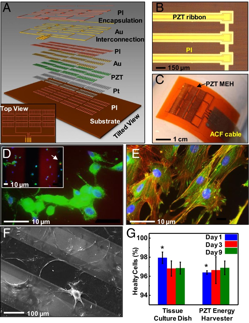
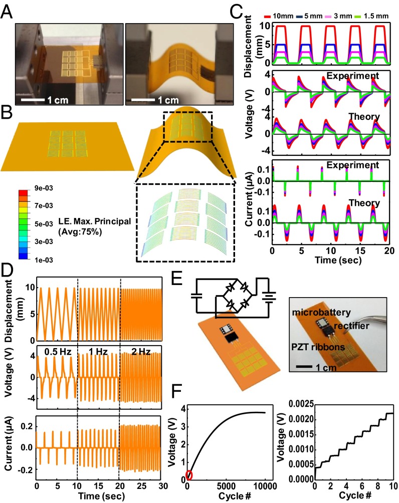
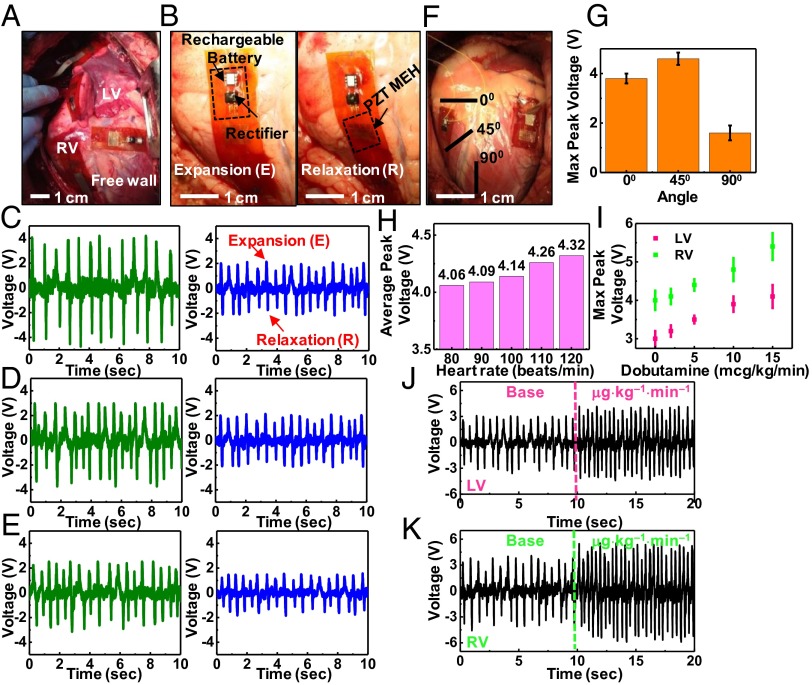
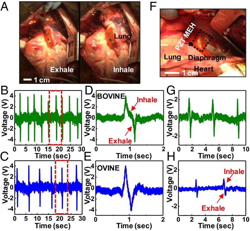
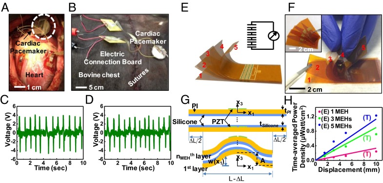
Here, we report advanced materials and devices that enable high-efficiency mechanical-to-electrical energy conversion from the natural contractile and relaxation motions of the heart, lung, and diaphragm, demonstrated in several different animal models, each of which has organs with sizes that approach human scales. A cointegrated collection of such energy-harvesting elements with rectifiers and microbatteries provides an entire flexible system, capable of viable integration with the beating heart via medical sutures and operation with efficiencies of ∼2%. Additional experiments, computational models, and results in multilayer configurations capture the key behaviors, illuminate essential design aspects, and offer sufficient power outputs for operation of pacemakers, with or without battery assist.

Keywords: biomedical implants; flexible electronics; heterogeneous integration; transfer printing; wearable electronics.


Conflict of interest statement

The authors declare no conflict of interest.

Figures

Fig. 1.
Fig. 1.
Flexible MEH based on thin ribbons of PZT, and tests of biocompatibility using rat smooth muscle cells. (A) Exploded-view schematic illustration with a top view (Inset). (B) Optical microscope image of PZT ribbons printed onto a thin film of PI. (C) Photograph of a flexible PZT MEH with cable for external connection. ACF, anisotropic conductive film. (D) Live/dead viability assay showing live cells (green) with intact nucleus (blue) and one dead cell (red) as indicated by the arrow (Inset). This image corresponds to day 9 of the experiment. (E) Fluorescent image showing Vinculin focal contact points (green), actin filaments (red), and nuclei (blue). (F) SEM image of cells on PZT ribbons encapsulated by a layer of PI. (G) Lactate dehydrogenase assay shows no indications of toxicity for cells on a membrane of PZT at day 9. (*P value ≤0.05 between the two groups.) Error bar is calculated standard error.
Fig. 2.
Fig. 2.
Experimental and theoretical studies of the electrical behavior of PZT MEHs under various mechanical loads. (A) Photographs of a PZT MEH clamped on a bending stage in flat (Left) and bent (Right) configurations. (B) Three-dimensional finite element method modeling for the device in A. The results highlighted by the black dashed box give the computed distributions of strain in the PZT ribbons for a displacement load of 5 mm along the horizontal direction. LE, logarithmic strain. (C) Experimental and theoretical results for displacement, voltage, and current as a function of time for PZT MEHs under bending loads similar to those shown in A and B. (D) Displacement, voltage, and current as a function of time curves, for bending loads with frequencies of 0.5, 1, and 2 Hz. (E) Schematic illustration (Left) and photograph (Right) of a PZT MEH connected to and cointegrated with a rectifier and rechargeable microbattery. A circuit schematic appears in Left. (F) Voltage across such a battery as a function of time during charging by a PZT MEH under cyclic bending load (Left). The peak voltage output of the PZT MEH is 4.5 V. The red oval (Left) highlights, approximately, the region plotted (Right). The results highlight the expected stepwise behavior in charging.
Fig. 3.
Fig. 3.
In vivo evaluation of the optimal placement and orientation of PZT MEHs on the heart, and assessment of voltage output by varying the heart rate via dobutamine infusion and use of a temporary pacemaker. (A) Photograph of PZT MEHs on the RV, LV, and free wall of a bovine heart. (B) PZT MEH cointegrated with a rectifier and rechargable battery, mounted on the RV of a bovine heart, shown during expansion (Left) and relaxation (Right). Open circuit voltage as a function of time for PZT MEHs on bovine (green) and ovine (blue) hearts, mounted on (C) RV, (D) LV, and (E) free wall at an orientation of 0° relative to the apex of the heart. Here, the heart rate is 80 beats per min. (F) Photograph of PZT MEHs oriented at different angles. (G) Measurements of maximum values of the peak open circuit voltages produced by these devices indicate peak output at 45°. Error bar is calculated standard error. (H) Average peak voltages of a PZT MEH on the RV of a bovine heart at 0° for various heart rates (80–120 beats per min) controlled by a temporary pacemaker. (I) Maximum peak voltage for various dosages of dobutamine infusion, for the case of a device on the RV (green points) and LV (pink points) of a bovine heart at 0°. Error bar is calculated standard error. Voltage as a function of time for PZT MEHs on the LV (J) and RV (K) of a bovine heart, with a base and maximum dose of dobutamine.
Fig. 4.
Fig. 4.
In vivo evaluation of PZT MEHs on the lung and diaphragm. (A) Photograph of a PZT MEH cointegrated with a microbattery and rectifier, mounted on the bovine lung. Voltage as a function of time for such devices on the bovine (B) and ovine (C) lung. D and E show plots corresponding to the regions indicated by the red dashed boxes in B and C, respectively. (F) Photograph of a PZT MEH on the bovine diaphragm. Voltage as a function of time for such a device on the bovine (G) and ovine (H) diaphragm.
Fig. 5.
Fig. 5.
Performance of a PZT MEH evaluated with the chest open and closed and scaling of power output in multilayer stacked designs. Photograph of a PZT MEH without and with battery, rectifier, and pacemaker connection on a bovine heart when the chest is (A) open and (B) closed. Voltage as a function of time for a PZT MEH on the bovine RV with the chest open (C) and closed (D). (E) Schematic illustration of a multilayer stack of five independent PZT MEHs connected in series. A circuit schematic appears in the upper right-hand corner. (F) Photograph of such a stacked configuration, peeled apart at the left edge to show the separate layers. Each device appears just before stacking (Inset). (G) Schematic illustration of the theoretical shape for buckling of a stack of PZT MEHs with spin-cast layers of silicone elastomer (thickness = 10 μm) in-between and under compression. (H) Time-averaged power density as a function of the bending load displacement for stacks consisting of one (pink curve), three (green curve) and five (blue curve) PZT MEHs, connected in series. E, experimental data; T, theory.

References

    1. Karami MA, Inman DJ. Powering pacemakers from heartbeat vibrations using linear and nonlinear energy harvesters. Appl Phys Lett. 2012;100(4):042901.
    1. Starner T. Human-powered wearable computing. IBM Syst J. 1996;35(3.4):618–629.
    1. Halámková L, et al. Implanted biofuel cell operating in a living snail. J Am Chem Soc. 2012;134(11):5040–5043. - PubMed
    1. Mercier PP, Lysaght AC, Bandyopadhyay S, Chandrakasan AP, Stankovic KM. Energy extraction from the biologic battery in the inner ear. Nat Biotechnol. 2012;30(12):1240–1243. - PMC - PubMed
    1. Wong LS, et al. A very low-power CMOS mixed-signal IC for implantable pacemaker applications. IEEE J Solid-State Circuits. 2004;39(12):2446–2456.

Publication types